B-276 Cisco 7000 Hardware Installation and Maintenance
Interface Processor LEDs
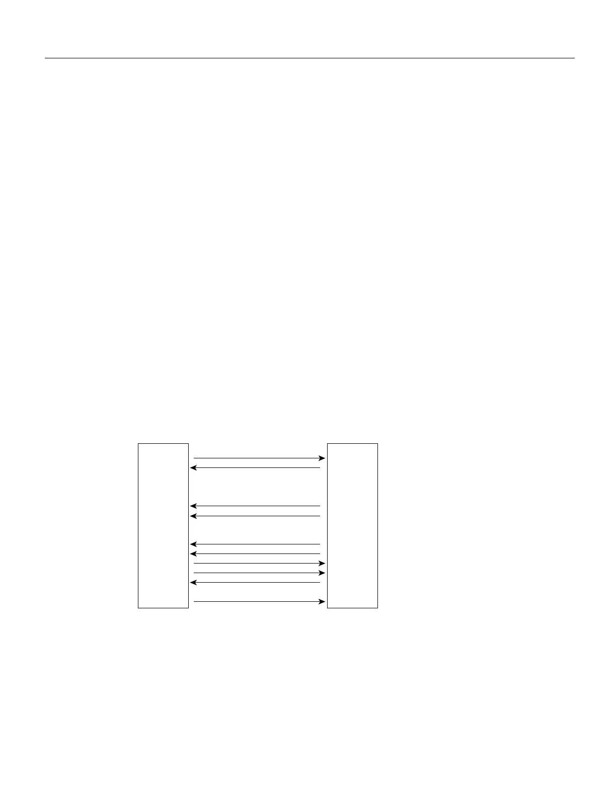
Figure B-12 shows the signal flow between a DTE and DCE device and the LEDs that correspond
to signals for each mode. The following LED state descriptions include the meanings for both DTE
and DCE interfaces.
• RxC— On DTE interfaces, this LED is on when the port is receiving a TxC signal from the
remote DCE device, which is usually a DSU or modem.
On DCE interfaces, this LED indicates TxC. This LED is on when the DCE port is sending a TxC
signal to the remote DTE device.
• RxD—On DTE interfaces, this LED is on when the port is receiving data signals (packets) from
the network through the remote DCE device. This LED is also on when it detects an idle pattern
that is commonly sent across the network during idle time.
On DCE interfaces, this LED indicates TxD. During normal DCE operation, this LED is on when
the DCE port is receiving data packets from the network through the remote DTE device.
• TxC—On DTE interfaces, this LED is on when the port is receiving the transmit clock signal
from the remote DCE.
On DCE interfaces, this LED indicates RxC. During normal DCE operation, this LED is on when
the DCE port is sending the internal clock signal (which the FSIP generates) to the remote DTE
device, which is usually a host, PC, or another router.
• Conn—On both DTE and DCE interfaces, this LED is on to indicate normal operation: the FSIP
is properly connected to the external device, and TA (DTE available) and CA (DCE available)
are active. When this LED is off, the FSIP is in loopback mode or is not connected to the network
or external device. (See Table B-2.)
Figure B-12 DTE to DCE Signals
The default mode for all interface ports without a port adapter cable attached is DCE, although there
is no default clock rate set on the interfaces. The DCE default allows you to perform local loopbacks
without having to terminate the port or connect a cable. Because the serial adapter cables determine
the mode and interface type, the FSIP port becomes a DTE when a DTE cable is connected to it. If
a DTE cable is connected to a port with a clockrate set, the DTE will ignore the clockrate and use
the external clock signal that is sent from the remote DCE.
TxC
RxC
RxD
TxD
TxC
RxC
RxD
DCD
DSR
DTR
RTS
CTS
LL
RxD
RxC
TxC
DTE DCE
H1612a

 Loading...


