Reading LED Indicators B-275
Interface Processor LEDs
FSIP LEDs
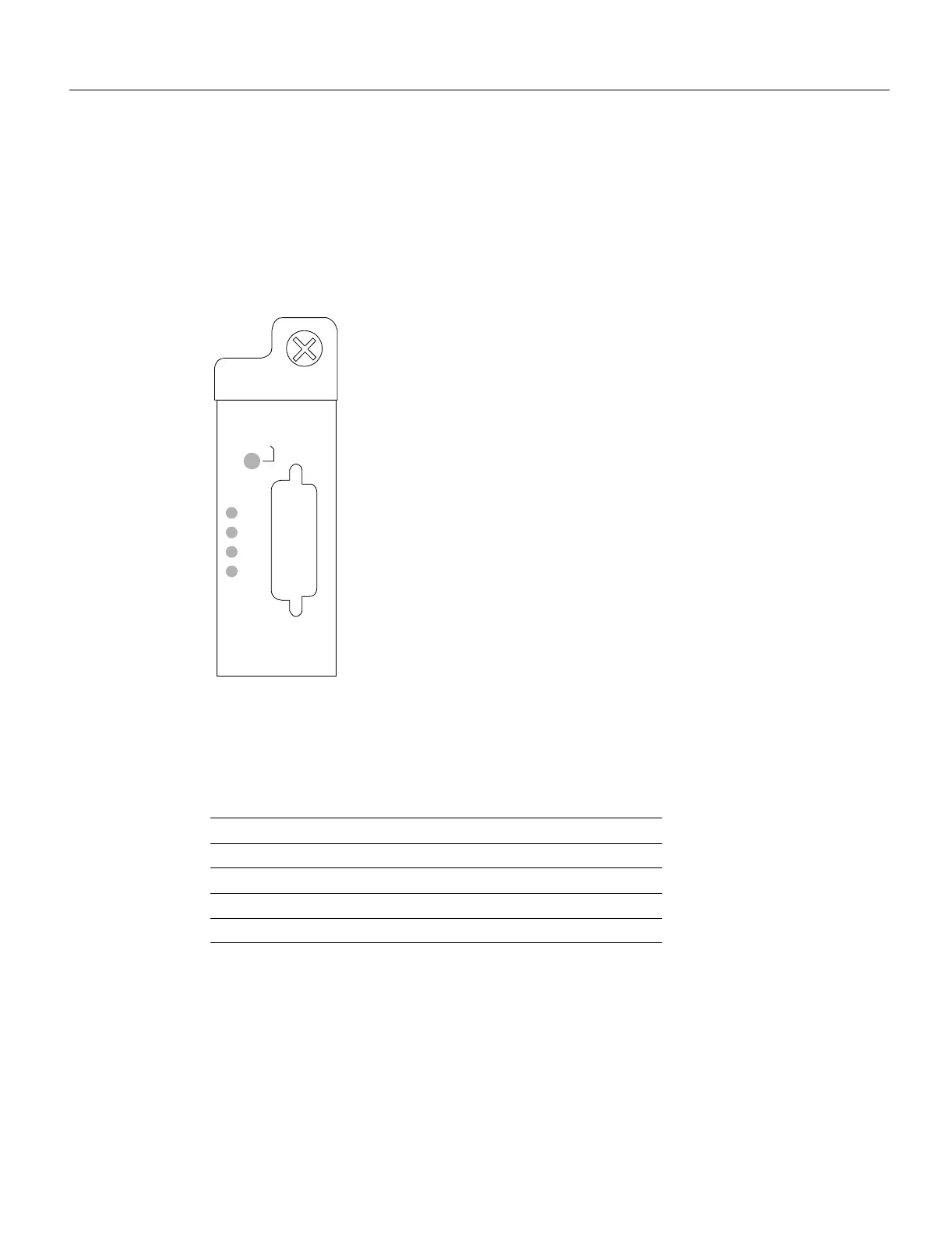
The FSIP LEDs are shown in Figure B-11. As with the other interface processors, the enabled LED
goes on to indicate that the FSIP is enabled for operation. However, unlike the LED cluster at the top
of the other interface processors, the LEDs for each serial port are adjacent to the connector.
Table B-2 lists descriptions of each LED.
Figure B-11 FSIP LEDs
The Conn (connected) LED goes on when the interface is connected to the network. During normal
operation, the three other LEDs light to indicate data and timing signal traffic, or an idle pattern that
is commonly sent across the line during idle time.
Table B-2 FSIP LEDs
The labels on each LED indicate the signal state when the FSIP port is in DTE mode. However, the
direction of the signals is reversed when the FSIP port is in DCE mode. For example, a DCE device
usually generates a clock signal, which it sends to the DTE device. Therefore, when the Receive
Clock (RxC) LED goes on, on a DTE interface, it indicates that the DTE is receiving the clock signal
from the DCE device. However, when the RxC LED goes on, on a DCE interface, it indicates that
the DCE is sending a clock signal (RxC) to the DTE device. Because of limited space on the FSIP
faceplate, only DTE mode states are labeled on each port.
LED DTE Signal DCE Signal
RxC Receive Clock (from DTE) (TxC) Transmit Clock (to DTE)
RxD Receive Data (from DTE) (TxD) Transmit Data (from DTE)
TxC Transmit Clock (from DCE) (RxC) Receive Clock (to DTE)
Conn Connected Connected
ENABLED
H1364a
-RxC
-RxD
-TxC
-Conn

 Loading...


