Preparing for Installation 2-81
Site Requirements
• Install heavier equipment in the lower half of the rack to maintain a low center of gravity.
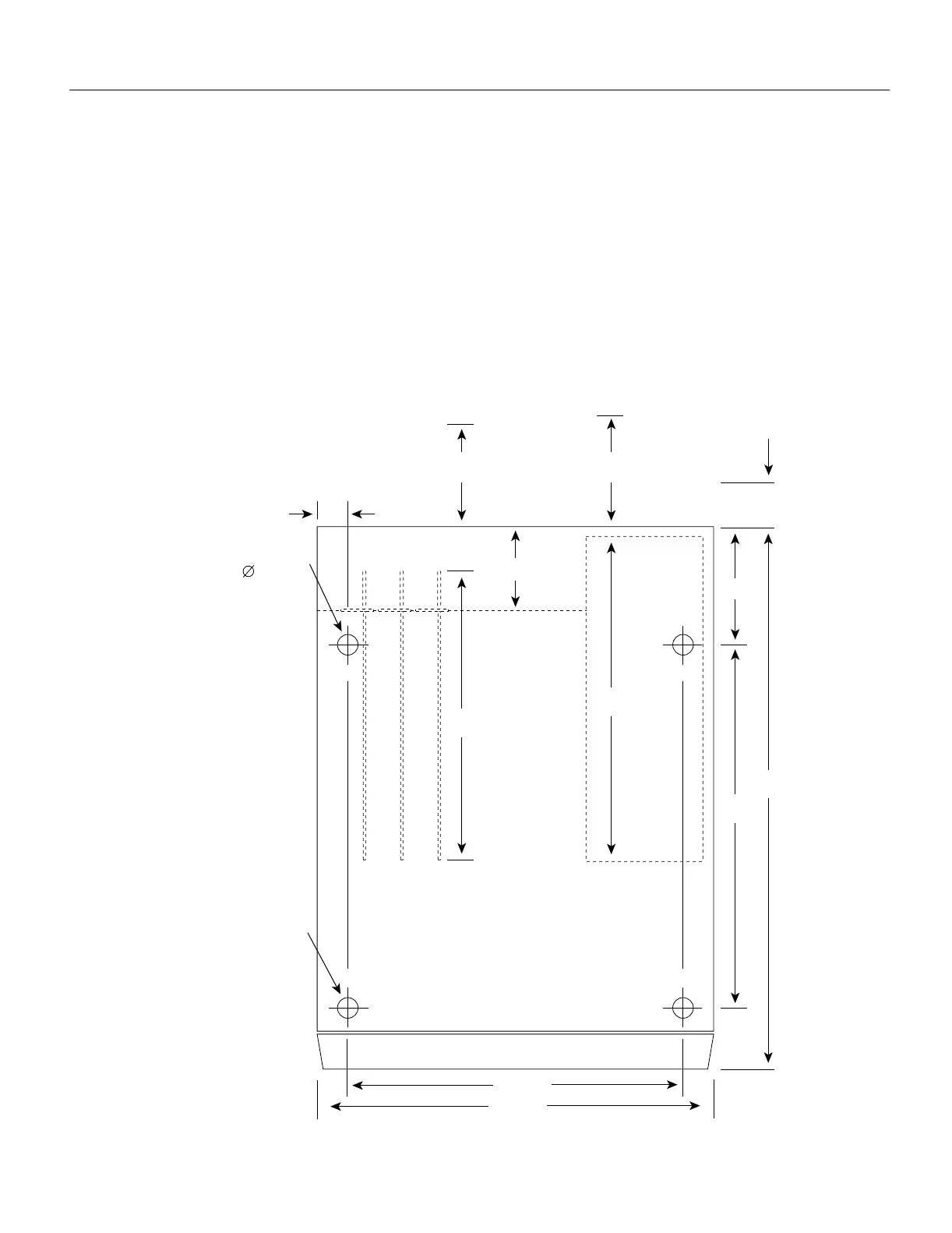
• If you plan to use an equipment shelf, ensure that the shelf is constructed to support the weight
and dimensions of the chassis. Figure 2-3 shows the chassis footprint, which you will need if you
are designing a customized shelf.
• Install the router in an open rack whenever possible. If installation in an enclosed rack is
unavoidable, ensure that the rack has adequate ventilation or an exhaust fan.
In addition to the preceding guidelines, review the precautions for avoiding overtemperature
conditions in the section Equipment-Rack Ventilation in this chapter.
Figure 2-3 Chassis Footprint and Outer Dimensions
15.060"
5.095"
16.916"
1.220"
Plastic front panel end
Foot diameter
1.125
4 places
Power supply/interface processor end
Foot thread size
5/16"
4 places
H1608a
25"
17.5"
4"
16"
13"
16" clearance required
for power supply removal
10" clearance required for
interface processor removal
(28" including
power cord)
 Loading...