365
Cisco Systems, Inc. www.cisco.com
Configuring Resilient Ethernet Protocol
Information About Configuring REP
REP
Resilient Ethernet Protocol (REP) is a Cisco proprietary protocol that provides an alternative to Spanning Tree Protocol
(STP) to control network loops, handle link failures, and improve convergence time. REP controls a group of ports
connected in a segment, ensures that the segment does not create any bridging loops, and responds to link failures
within the segment. REP provides a basis for constructing more complex networks and supports VLAN load balancing.
One REP segment is a chain of ports connected to each other and configured with a segment ID. Each segment consists
of standard (non-edge) segment ports and two user-configured edge ports. A switch can have no more than two ports
that belong to the same segment, and each segment port can have only one external neighbor. A segment can go
through a shared medium, but on any link only two ports can belong to the same segment. REP is supported only on
Layer 2 trunk interfaces.
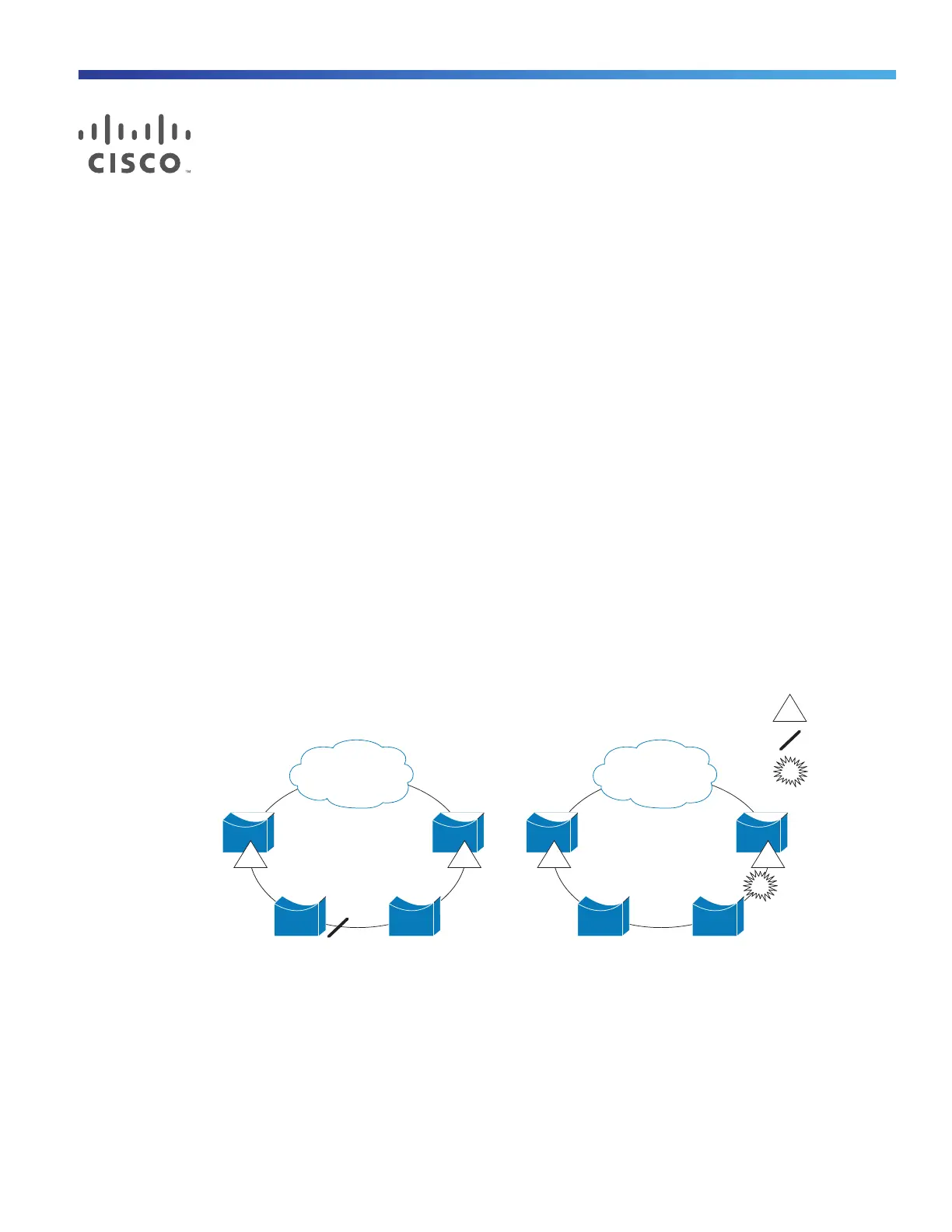
Figure 52 on page 365 shows an example of a segment consisting of six ports spread across four switches. Ports E1
and E2 are configured as edge ports. When all ports are operational (as in the segment on the left), a single port is
blocked, shown by the diagonal line. When there is a failure in the network, as shown in the diagram on the right, the
blocked port returns to the forwarding state to minimize network disruption.
Figure 52 REP Open Segments
The segment shown in Figure 52 on page 365 is an open segment; there is no connectivity between the two edge ports.
The REP segment cannot cause a bridging loop and it is safe to connect the segment edges to any network. All hosts
connected to switches inside the segment have two possible connections to the rest of the network through the edge
ports, but only one connection is accessible at any time. If a failure causes a host to be unable to access its usual
gateway, REP unblocks all ports to ensure that connectivity is available through the other gateway.
The segment shown in Figure 53 on page 366, with both edge ports located on the same switch, is a ring segment. In
this configuration, there is connectivity between the edge ports through the segment. With this configuration, you can
create a redundant connection between any two switches in the segment.
E2E1 E2E1
E1
Edge port
Blocked port
Link failure
201888

 Loading...