-768
Cisco Industrial Ethernet 4000 Series Switch Software Configuration Guide
Chapter Configuring HSRP and VRRP
Understanding HSRP
router interfaces running HSRP. The router selected by the protocol to be the active router receives and
routes packets destined for the group’s MAC address. For n routers running HSRP, there are n +1 IP and
MAC addresses assigned.
HSRP detects when the designated active router fails, and a selected standby router assumes control of
the Hot Standby group’s MAC and IP addresses. A new standby router is also selected at that time.
Devices running HSRP send and receive multicast UDP-based hello packets to detect router failure and
to designate active and standby routers. When HSRP is configured on an interface, Internet Control
Message Protocol (ICMP) redirect messages are disabled by default for the interface.
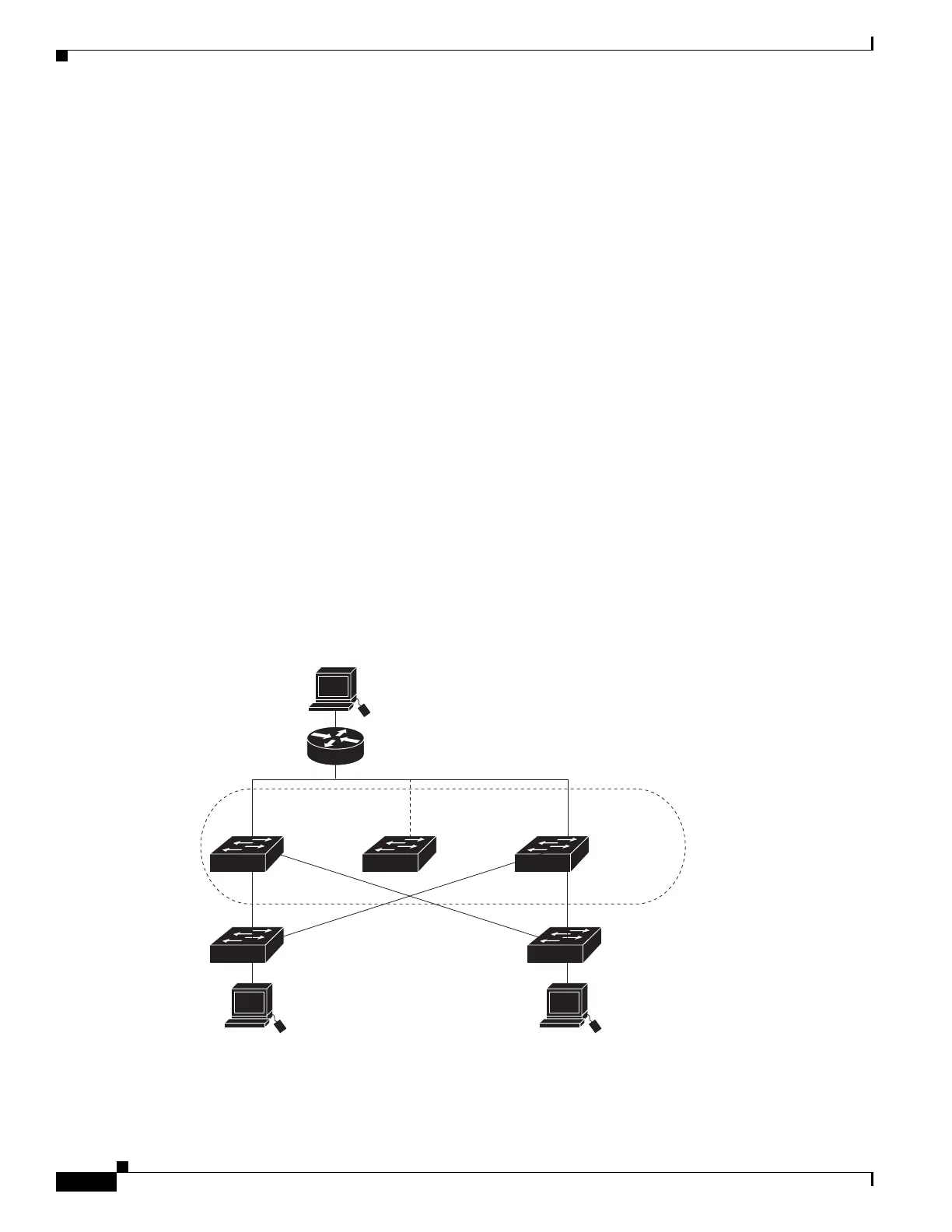
You can configure multiple Hot Standby groups among switches that are operating in Layer 3 to make
more use of the redundant routers. To do so, specify a group number for each Hot Standby command
group you configure for an interface. For example, you might configure an interface on switch 1 as an
active router and one on switch 2 as a standby router and also configure another interface on switch 2 as
an active router with another interface on switch 1 as its standby router.
Figure 47-94 shows a segment of a network configured for HSRP. Each router is configured with the
MAC address and IP network address of the virtual router. Instead of configuring hosts on the network
with the IP address of Router A, you configure them with the IP address of the virtual router as their
default router. When Host C sends packets to Host B, it sends them to the MAC address of the virtual
router. If for any reason, Router A stops transferring packets, Router B responds to the virtual IP address
and virtual MAC address and becomes the active router, assuming the active router duties. Host C
continues to use the IP address of the virtual router to address packets destined for Host B, which Router
B now receives and sends to Host B. Until Router A resumes operation, HSRP allows Router B to
provide uninterrupted service to users on Host C’s segment that need to communicate with users on Host
B’s segment and also continues to perform its normal function of handling packets between the Host A
segment and Host B.
Figure 47-94 Typical HSRP Configuration
Host B
172.20.130.5
172.20.128.32
Host A
172.20.128.55
172.20.128.1 172.20.128.3 172.20.128.2
Virtual
router
Active
router
Standby
router
Router A Router B
204345
Host C

 Loading...