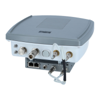
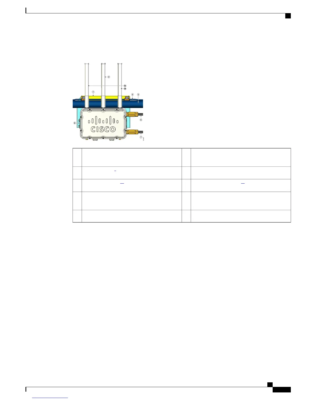
This figure shows antenna placement for a two-radio cable mesh access point.
Figure 10: 1522C Two Radio Cable Mesh Access Point Configuration (Hinged-Side Facing Forward)
Cable bundle5Clamp bracket with cable clamps (part of strand
mount kit, ordered separately)
1
Fiber-optic connection265-GHz antenna
9
(Tx/Rx)2
Cable POC power input
11
72.4-GHz antennas
10
(Tx/Rx)3a
Strand mount bracket (part of strand mount kit,
ordered separately)
82.4-GHz antennas (Rx)23b
Strand support cable4
9
Illustration shows antenna for an access point with two radios.
10
Liquid tight connector not shown.
11
Stinger connector shown is user-supplied.
Cisco Mesh Access Points, Design and Deployment Guide, Release 7.3
OL-27593-01 29
Mesh Network Components
Cisco Outdoor Mesh Access Points