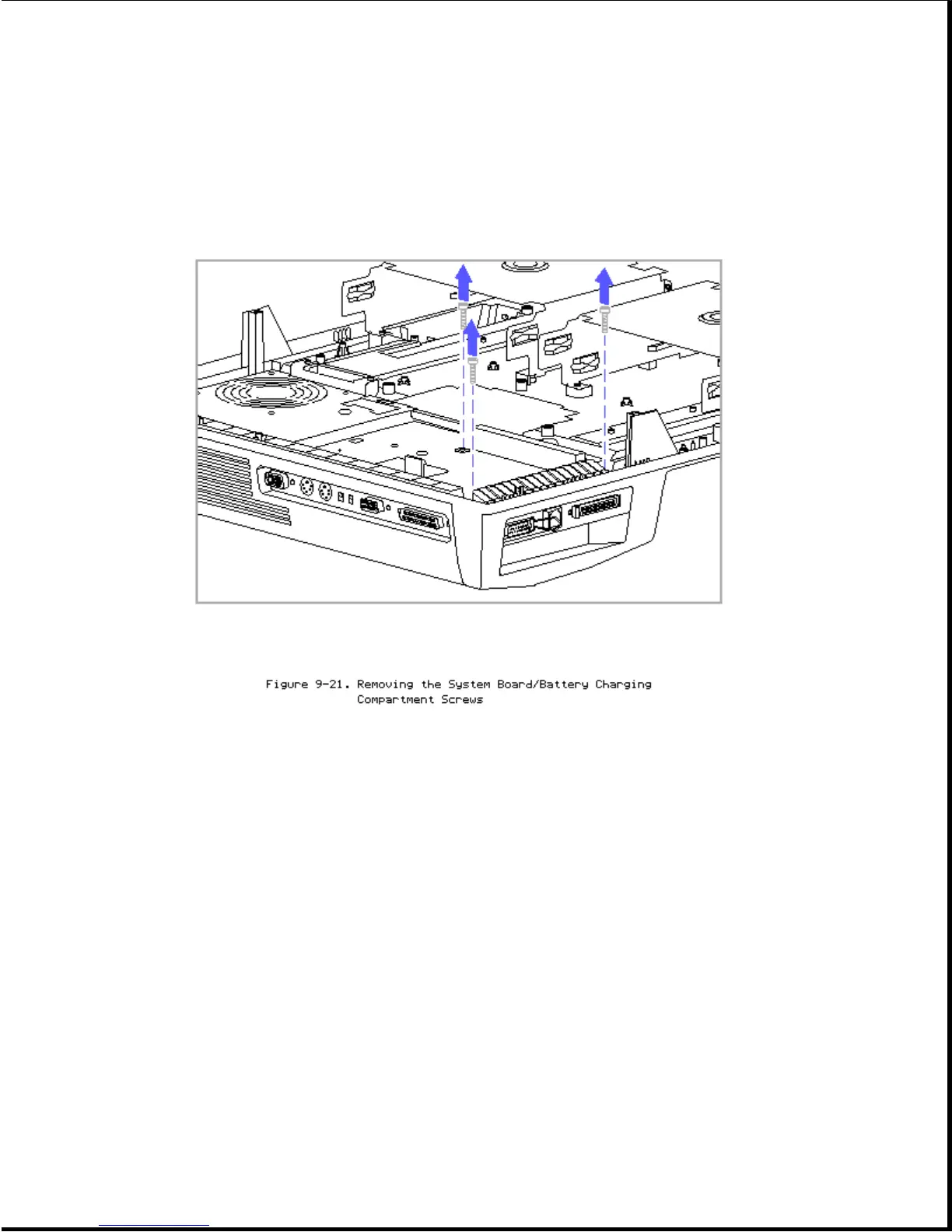
(Figure 9-19). If the three screws are tightened first, the
docking mechanism or the 198-pin external options connector
may not align properly.
9. To allow the latch on the AUI connector to clear the top cover, fold
the latch [1] so that it lies against the RJ-45 connector (Figure
9-22).
10. Lift the front of the system board/battery charging compartment
assembly up by the external options connector [2] until the connector
shield [3] is free of the top cover, then carefully tilt the assembly
back to release it from the top cover (Figure 9-22).