Cyan Z-Series Engineering and Planning Guide Release 5.0
700-0023-05-00 Rev. 1 © 2013 Cyan, Inc. – All Rights Reserved. Page 147
LAD-4/LAD-8/LAD-8i/LAD-8A/LAD-8E/LAD-8X
The minimum and maximum supported span loss (or link budget) for the LAD-4/8/i/A/E/X modules is
summarized in the table below.
Card Type Minimum Span Loss Maximum Span Loss Maximum Span Distance
@ 0.25 dB/km
LAD-4/LAD-8/LAD-8i 8 dB 16 dB 64 km
LAD-4A/LAD-8A 8 dB 24 dB 96 km
LAD-8E 8 dB 32 dB 128 km
LAD-8X 12 dB 40 dB 160 km
Note: The LAD-8E, at 128 km, and the LAD-8X, at 160 km, require dispersion compensation.
LAD-4/8/i/A/E/X Safety Defaults
By default, the LAD-4A/LAD-8A TX Post-Amp attenuator is set to 10 dB, the LAD-8E/LAD-8X TX
Post-Amp attenuator is set to 18 dB. This setting limits the maximum reach, but allows for some safety
margin when initially turning up optical fiber spans. Under the default settings, all LAD-4/LAD-8/LAD-8i,
LAD-4A/LAD-8A, LAD-8E outputs can be safely connected to another module of the same type with
10 dB of attenuation. Under the default settings, the LAD-8X can be safely connected to another module of
the same type with 12 dB of attenuation.
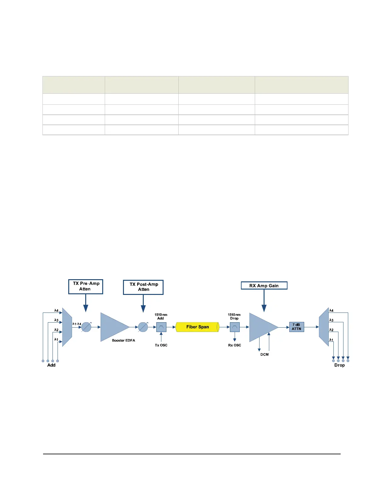
LAD-4/8/i/A/E/X Optical Control Points
The Z-Series LAD modules contain multiple gain control points that can be adjusted using the system
management software to optimize for the link optical characteristics.
The following diagram shows the location of the optical attenuation/gain control points for the LAD-8E
module.
Figure 75: LAD-8E Variable Optical Attenuator (VOA) Control Points