Cyan Z-Series Engineering and Planning Guide Release 5.0
700-0023-05-00 Rev. 1 © 2013 Cyan, Inc. – All Rights Reserved. Page 25
Z22 shelves should be installed in accordance with the Cyan Z22 Installation and Safety Guide. This will
ensure correct installation of modules, all associated wire management, power and grounding requirements,
and related components.
Redundancy and Protection
• Redundant fans
• Redundant power connections
• Equipment Protection: 1:1 for all common cards and service modules
• Carrier Ethernet Protection:
IEEE 802.3ad Link Aggregation
IEEE 802.3Qay Path Protection
ITU-T G.8032 Ethernet Ring Protection
• SONET/SDH Protection:
1+1 APS/MSP
UPSR/SNCP
1.1.2 Z22 Card Installation Guidelines
Z22 shelf slot restrictions and line card placement guidelines are shown in the tables below. CEMi controller
cards can only be installed in slots A and B. If deploying the in-chassis LAD-2P or LAD-2G module, you
must install the LAD module in slot B.
+24V Z22 Shelf
The PME-216i +24V I-Temp line card is identical in function to the -48V I-Temp PME-216i line card, but is
designed to operate in 24-volt applications supported by the Z22 +24V model. Voltage range for the +24
Volt PME-216i line card is 18 to 30 Vdc.
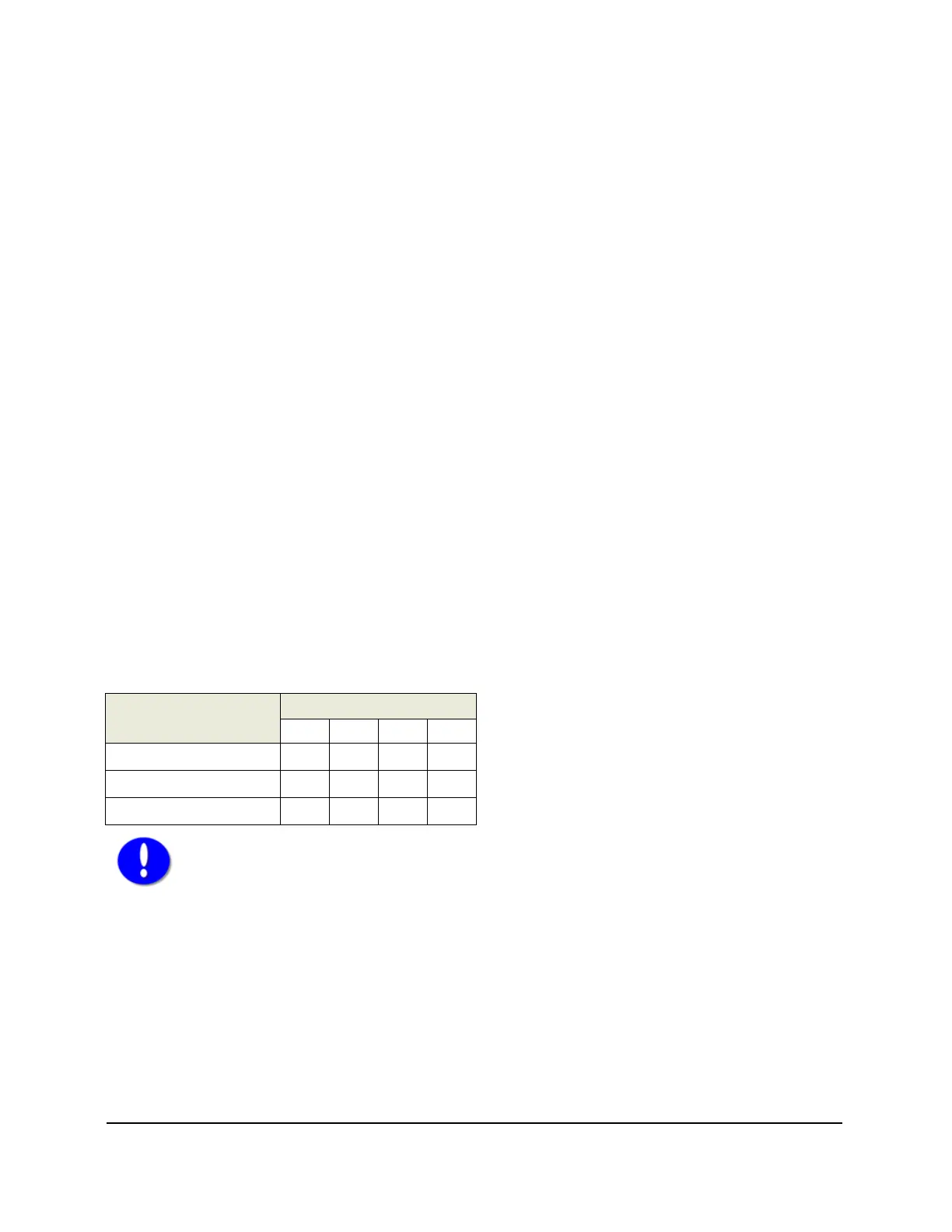
Line Cards
Slots
A B 1 2
CEMi X X
LAD-2P or LAD-2G X
PME-216i (+24V) X X
Important! – At least one PME-216i line card must be installed in slots 1 and/or 2 of the
+24V Z22 shelf to act as the shelf manager.