Cyan Z-Series Engineering and Planning Guide Release 5.0
Page 148 © 2013 Cyan, Inc. – All Rights Reserved. 700-0023-05-00 Rev. 1
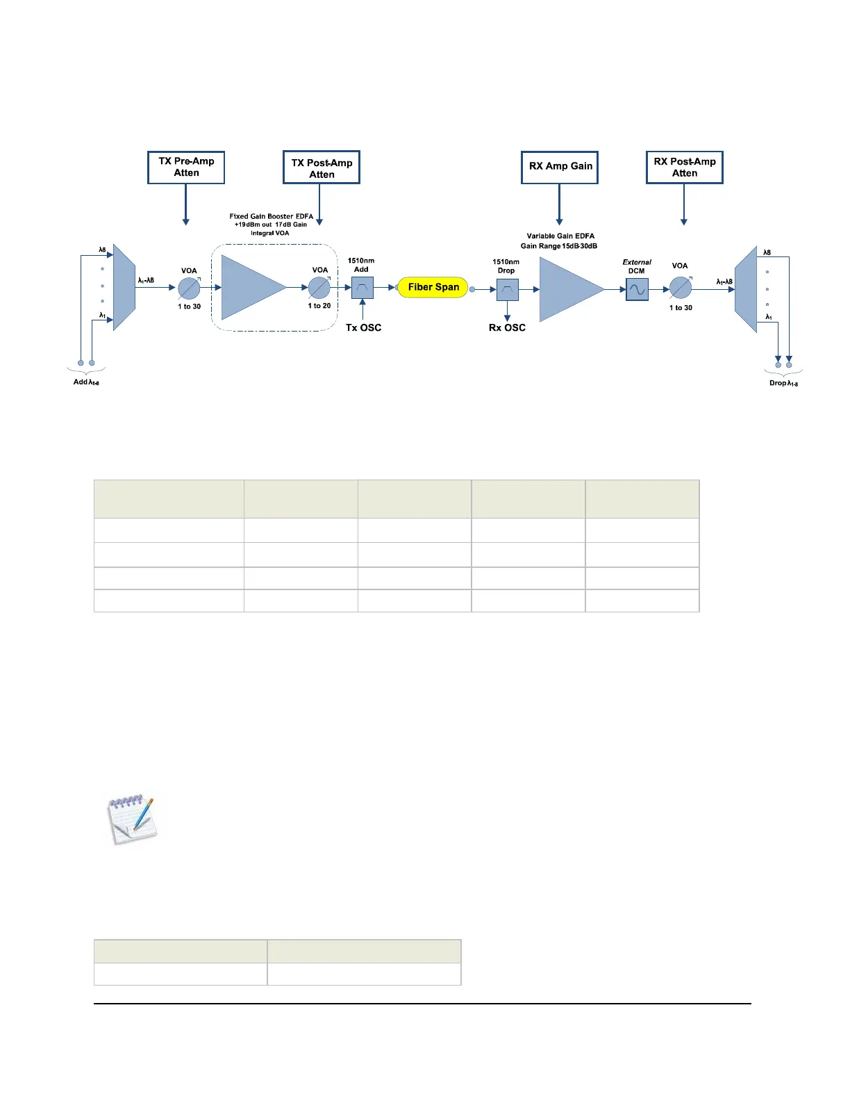
The following diagram shows the location of the optical attenuation/gain control points for the LAD-8X
module.
Figure 76: LAD-8X VOA Control Points
LAD-4/8/i/A/E/X Control Point Table
The following table shows which points of optical level control are available on each LAD-4/8 module:
Card Type
TX Pre-Amp
Attenuator
TX Post-Amp
Attenuator
RX Amp Gain
RX Post-Amp
Attenuator
LAD-4/LAD-8/LAD-8i
LAD-4A/LAD-8A X X
LAD-8E X X X
LAD-8X X X X X
The TX Pre-Amp Attenuator is included to allow control of optical levels at the input to the TX booster
amplifier.
The TX Post Amp Attenuator is used to limit the maximum transmit power.
The RX Amp Gain can be controlled to optimize the system gain for long spans in excess of 100 km.
The RX Post-Amp Attenuator can be used to adjust the RX Power at the XFP transceiver.
Configuring the LAD-8A Gain Parameters
Note: The default values should only be adjusted after consulting a Cyan system engineer to
determine the proper settings.
LAD-8A TX Pre-Amp attenuation should be set to 12.5 dB. This value should not be changed. This
guarantees a valid optical input to the TX Amplifier.
LAD-8A TX Post-Amp attenuation should be set based on span loss as shown in the table below.
TX Pre-Amp Attenuator TX Post-Amp Attenuator
12.5 Span Loss - 22