Cyan Z-Series Engineering and Planning Guide Release 5.0
Page 50 © 2013 Cyan, Inc. – All Rights Reserved. 700-0023-05-00 Rev. 1
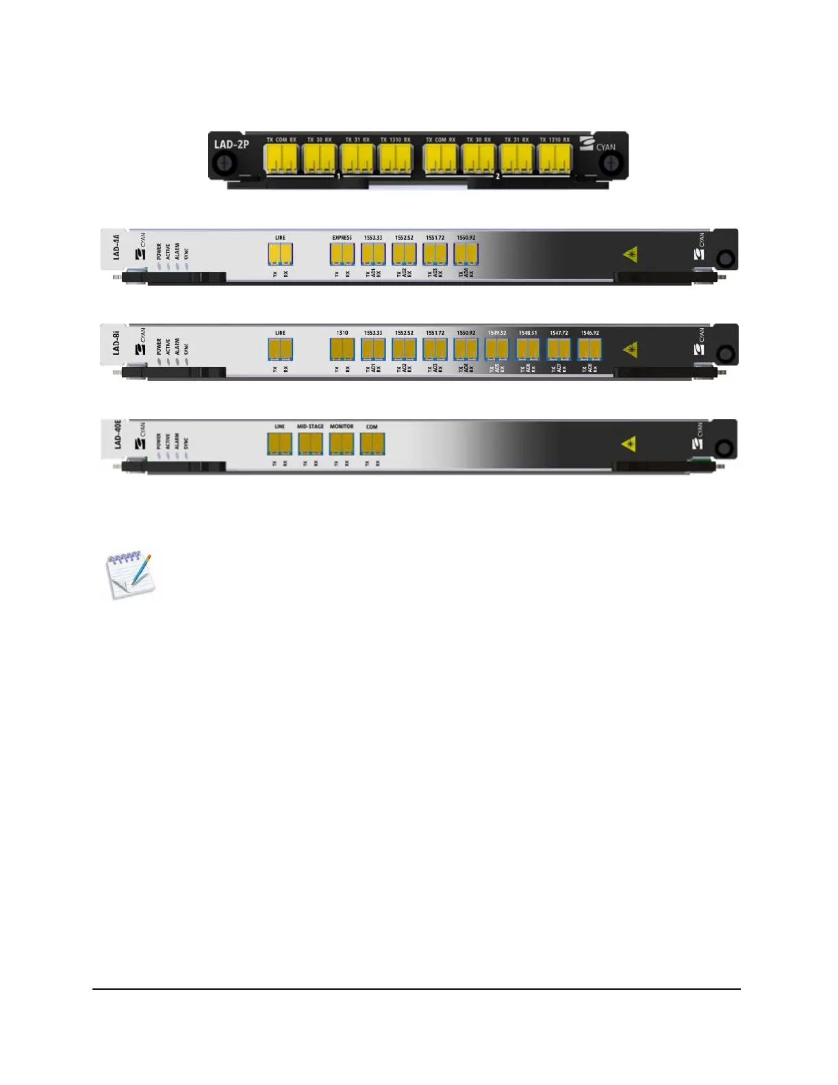
The following figures show some examples of the various LAD modules.
Figure 10: Cyan Z22 LAD-2P Module
Figure 11: Cyan Z-Series LAD-4A Module
Figure 12: Cyan Z-Series LAD-8i Module
Figure 13: Cyan Z-Series LAD-40E Module
For detailed information on optical link design for LAD modules, see Optical Link Design starting on page 145.
Note: LAD-8 to LAD-8A links are not supported.
LAD-40 and LAD-40E Modules Paired with the AWG-40
LAD-40 and LAD-40E modules require an associated AWG-40 Array Wave Guide module for add/drop
traffic. Individual wavelengths are added and/or dropped using the passive AWG-40 2
RU module. The
AWG-40 provides the ability to multiplex and de-multiplex any of the 40 channels supported by a LAD-40
or LAD-40E module. The AWG-40 module is connected to the LAD-40 or LAD-40E COM port through a
fiber jumper. The individual channels on the AWG-40 module are then connected to the appropriate
Z-Series line card DWDM XFP transceiver using a fiber jumper.