Cyan Z-Series Engineering and Planning Guide Release 5.0
Page 32 © 2013 Cyan, Inc. – All Rights Reserved. 700-0023-05-00 Rev. 1
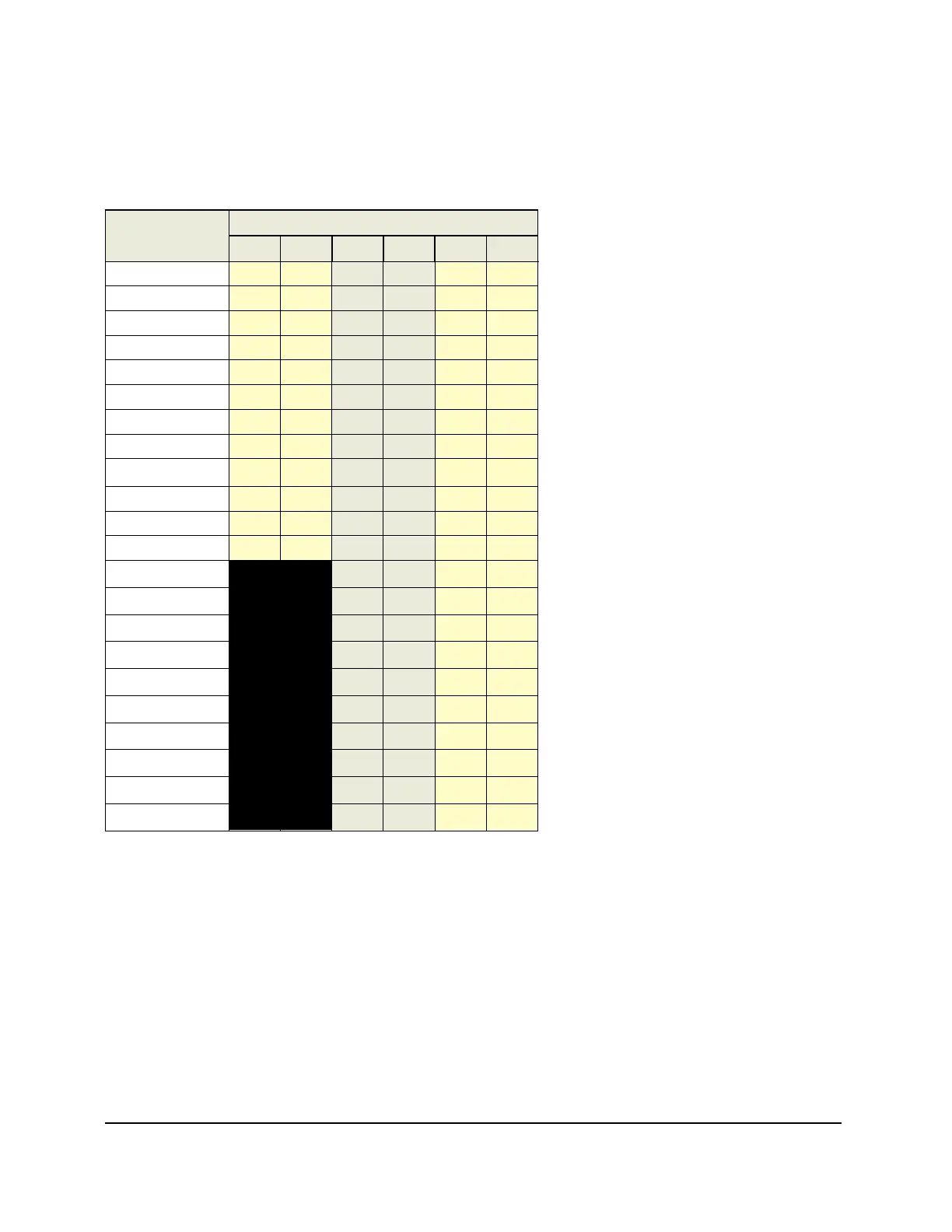
1.2.2 Z33 Line Card Configuration Guidelines
Z33 slot restrictions and line card placement guidelines are shown in the table below. Note that slots A and
B are reserved for the Common Equipment Modules (CEMi’s) and are not shown in the table. Card pairs,
where applicable, can be installed in slot 1/2, 3/4, and 5/6.
Line Cards
Slots *
1 2 3 4 5 6
2.5G-LME4 X X X X X X
DTM-8 X X X X X X
DTM-8G X X X X X X
DTM-100G X X X X X X
PME-216i X X X X X X
PME-412 X X X X X X
SFT-8 X X X X X X
SFT-10G16 X X X X X X
MSE-1482 X X X X X X
FLX-216i X X X X X X
WSS-402 X X X X X X
WSS-404 X X X X X X
LAD-4 X X X X
LAD-4A
X X X X
LAD-8 X X X X
LAD-8A X X X X
LAD-8E
X X X X
LAD-8i X X X X
LAD-8X X X X X
LAD-40 X X X X
LAD-40E
X X X X
LAC-8 X X X X
* Shading indicates paired slots for applicable line cards.
At least one of the following line cards must be installed in slots 1 and/or 2 of the Z33 shelf:
• 2.5G-LME4 • PME-216i • MSE-1482
• DTM-8 • PME-412 • WSS-402
• DTM-8G • SFT-8 • WSS-404
• SFT-10G16 • FLX-216i • DTM-100G
When installed in slots 1 and/or 2, these cards also act as shelf managers.