Cyan Z-Series Engineering and Planning Guide Release 5.0
Page 36 © 2013 Cyan, Inc. – All Rights Reserved. 700-0023-05-00 Rev. 1
Pin Description
7 T1/E1 RX2_+ (Input)
8 T1/E1 RX2_- (Input)
9 CC/2M RX1_+ (Input)
10 CC/2M RX1_- (Input)
11 CC/2M RX2_+ (Input)
12 CC/2M RX2_- (Input)
1.2.5 Z33 Alarms
The Z33 platform supports system and environmental alarms. System alarms include Critical, Major,
Minor, Audible, Failsafe, and ACO. The environmental alarms include 4 inputs and 2 outputs. Alarms are
accessed through a 12-position pluggable terminal block on the rear side of the Z33 chassis.
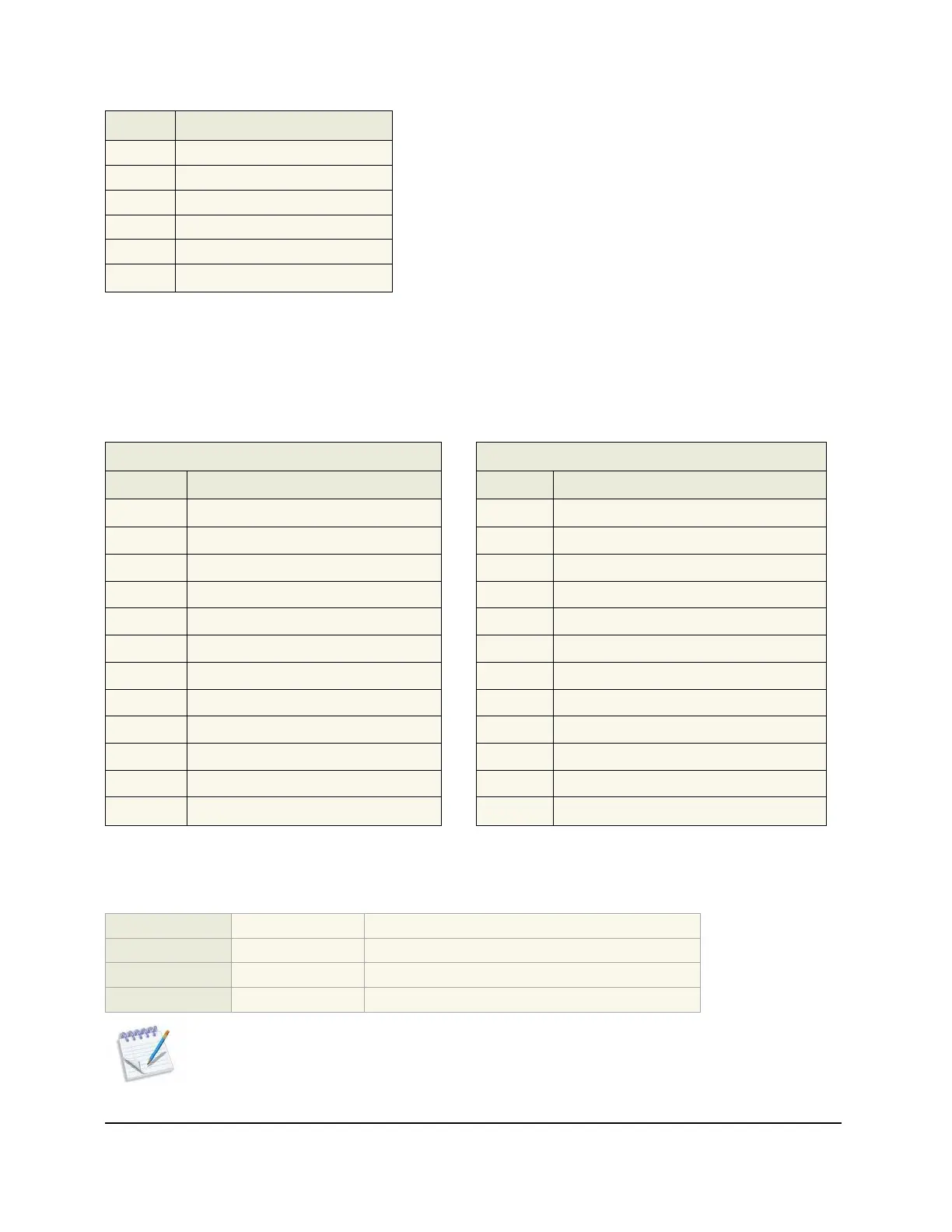
The following table shows the connector pinouts for the system and environmental alarms:
System Alarm Connector Pinout
Environmental Alarm Connector Pinout
Pin Description
Pin Description
1 CRIT_NO
1 OUT1_NO
2 CRIT_C
2 OUT1_C
3 MAJ_NO
3 OUT2_NO
4 MAJ_C
4 OUT2_C
5 MIN_NO
5 IN1_+
6 MIN_C
6 IN1_COM
7 AUD_NO
7 IN2_+
8 AUD_C
8 IN2_COM
9 FAIL_NC
9 IN3_+
10 FAIL_C
10 IN3_COM
11 ACO_+
11 IN4_+
12 ACO_COM
12 IN4_COM
For details on configuring environmental alarms, see the Troubleshooting and Maintenance Guide.
1.2.6 Z33 Shelf Power
Feeds:
2 1-A & 1-B
Voltage range:
-40 to -60 Vdc Guaranteed Operation
Max voltage:
-/+100 Vdc Non-operational, no damage
Max current:
24 Amps
Note: Use Planet Design as a guideline based on the total configured system current draw.
You must size fuses according to NEC standards or local site practice.