Cyan Z-Series Engineering and Planning Guide Release 5.0
700-0023-05-00 Rev. 1 © 2013 Cyan, Inc. – All Rights Reserved. Page 43
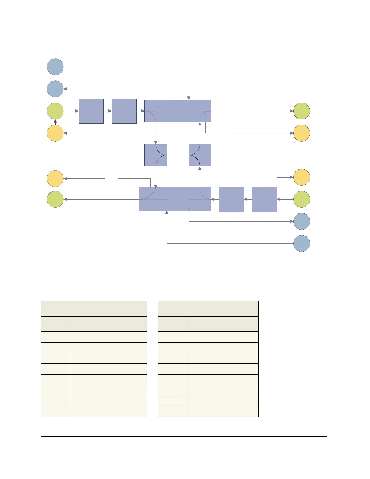
The graphic below shows the L-AMP block diagram.
TX Tap
Variable
Optical
Attenuator
EDFA
Variable
Optical
Attenuator
EDFA
1510 nm
OSC
SFP
1510 nm
OSC
SFP
RX
RX
DCF
In
DCF
Out
DCF
Out
DCF
In
TX
TX
East
Optical
Supervisory
Channel
West
Optical
Supervisory
Channel
RX
Mon
RX Tap
TX
Mon
TX Tap
RX
Mon
RX Tap
TX
Mon
West
East
1510nm
Add
1510nm
Drop
1%
Tap
1%
Tap
1510nm
Add
1510nm
Drop
Figure 9: L-AMP Block Diagram
1.4.1 L-AMP Shelf Pinouts
The L-AMP shelf pinouts for the input and output alarms connector are shown in the following tables:
Input Alarms Connector
Output Alarms Connector
Pin Description
Pin Description
8 IN3_COM
8 FAIL_COM
7 IN3_+
7 FAIL_NC
6 IN2_COM
6 AUD_COM
5 IN2_+
5 AUD_NO
4 IN1_COM
4 OUT2_COM
3 IN1_+
3 OUT2_NO
2 ACO_COM
2 OUT1_COM
1 ACO_+
1 OUT1_NO
The external alarm inputs and outputs are all software configurable.