Cyan Z-Series Engineering and Planning Guide Release 5.0
Page 202 © 2013 Cyan, Inc. – All Rights Reserved. 700-0023-05-00 Rev. 1
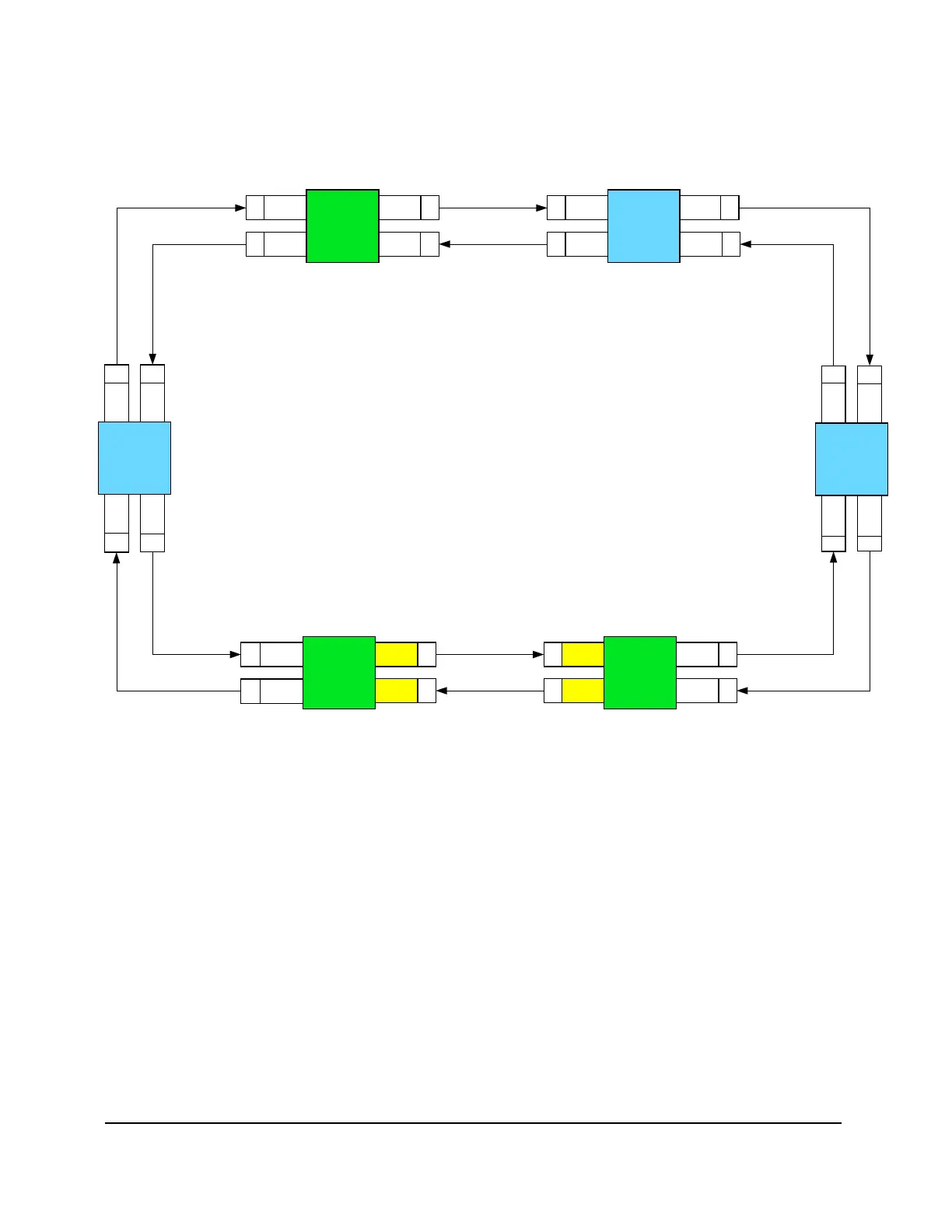
The next figure shows a typical Z33/Z77 ring configuration with odd to even slots connected in a clockwise
direction. Z33 LAD and WSS cards are installed top down. Z77 LAD and WSS cards are installed right to
left.
T
X
R
X
R
X
LAD-8
Slot 16
R
X
T
X
Site 1
Z77
LAD-8
Slot 15
LAD-8
Slot 16
LAD-8
Slot 15
T
X
LAD-8
Slot 6
R
X
T
X
Site 2
Z33
LAD-8
Slot 5
LAD-8
Slot 6
LAD-8
Slot 5
R
X
T
X
LAD-8
Slot 15
R
X
Site 5
Z77
WSS
Slot 16
T
X
R
X
T
X
Site 4
Z77
Lad-8
Slot 16
R
X
T
X
LAD-8
Slot 6
R
X
T
X
LAD-8
Slot 5
LAD-8
Slot 6
R
X
T
X
LAD-8
Slot 6
R
X
T
X
Site 6
Z33
LAD-8
Slot 5
LAD-8
Slot 6
LAD-8
Slot 5
R
X
T
X
WSS
Slot 16
WSS
Slot 15
WSS
Slot 15
Lad-8
Slot 16
LAD-8
Slot 15
LAD-8
Slot 5
Site 3
Z33
Figure 112: Typical Z33 and Z77 Ring Configuration