Cyan Z-Series Engineering and Planning Guide Release 5.0
Page 150 © 2013 Cyan, Inc. – All Rights Reserved. 700-0023-05-00 Rev. 1
LAD-40 and LAD-40E Link Budget
The minimum and maximum attenuation (or link budget) for the LAD-40 and LAD-40E modules is
summarized in the table below.
Card Type Minimum Span Loss Maximum Span Loss Maximum Span Distance
@ 0.25 dB/km
LAD-40 0 dB 10 dB 40 km
LAD-40E 8 dB 28 dB 112 km
Note: The LAD-40E, at 112 km, requires dispersion compensation.
LAD-40E Safety Defaults
By default, the LAD-40E TX Post-Amp attenuator is set to 18 dB and the RX Pre-Amp attenuator is set to
5 dB. This setting limits the maximum reach, but allows for some safety margin when initially turning up
optical fiber spans. Under the default settings, the LAD-40E output can be safely connected to another
module of the same type with 10 dB of attenuation.
LAD-40 and LAD-40E Optical Control Points
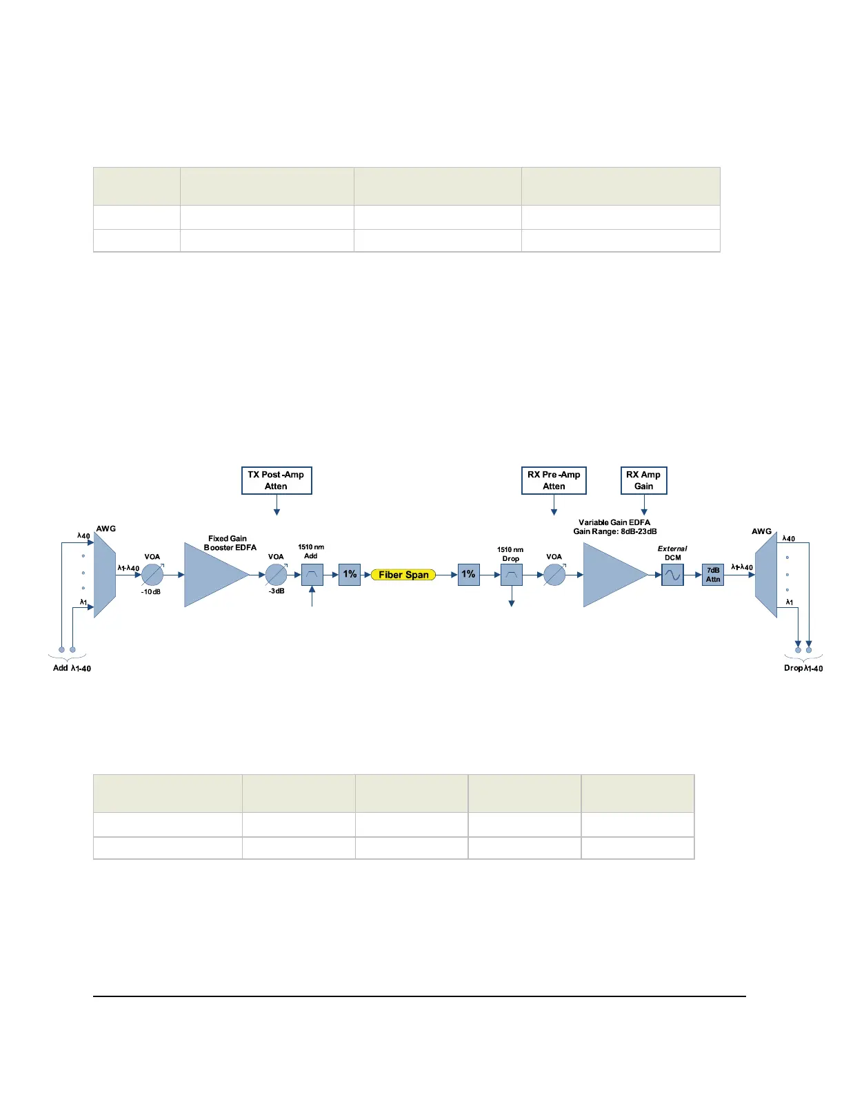
The following diagram shows the location of the optical attenuation/gain control points for the LAD-40E module.
Figure 77: LAD-40E VOA Control Points
LAD-40 and LAD-40E Control Point Table
The following table shows which points of optical level control are available on each LAD-40 and
LAD-40E module.
Card Type
TX Pre-Amp
Attenuator
TX Post-Amp
Attenuator
RX Amp Gain
RX Pre-Amp
Attenuator
LAD-40
LAD-40E X X X X
The TX Pre-Amp Attenuator is included to allow control of optical levels at the input to the TX booster
amplifier.
The TX Post Amp Attenuator is used to limit the maximum transmit power.
The RX Amp Gain can be controlled to optimize the system gain for long spans in excess of 100 km.
The RX Pre-Amp Attenuator can be used to allow control of optical levels at the input to the RX amplifier.