Cyan Z-Series Engineering and Planning Guide Release 5.0
Page 178 © 2013 Cyan, Inc. – All Rights Reserved. 700-0023-05-00 Rev. 1
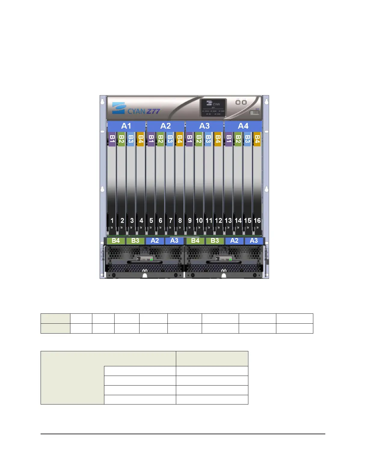
5.5 Z77 Fuse Positions and DC Feeds
Z77 (shelf v2) Fuse Positions
The figure shows the eight DC feeds that are distributed across the sixteen Z77 (shelf v2) line card slots and
the two fan modules in a redundant fashion.
Figure 97: Z77 Fuse Assignment for Fan Module
The table below shows the DC feeds and their associated Z77 line card slots.
DC Feeds A1 A2 A3 A4 B1 B2 B3 B4
Slots
1 – 4 5 – 8 9 – 12 13 – 16 1, 5, 9, 13 2, 6, 10, 14 3, 7, 11, 15 4, 8, 12, 16
The table below shows the DC feeds and their associated redundant fan modules.
Fan Module #1 Fan Module #2
DC Feeds
B4 B4
B3 B3
A2 A2
A3 A3