Cyan Z-Series Engineering and Planning Guide Release 5.0
700-0023-05-00 Rev. 1 © 2013 Cyan, Inc. – All Rights Reserved. Page 203
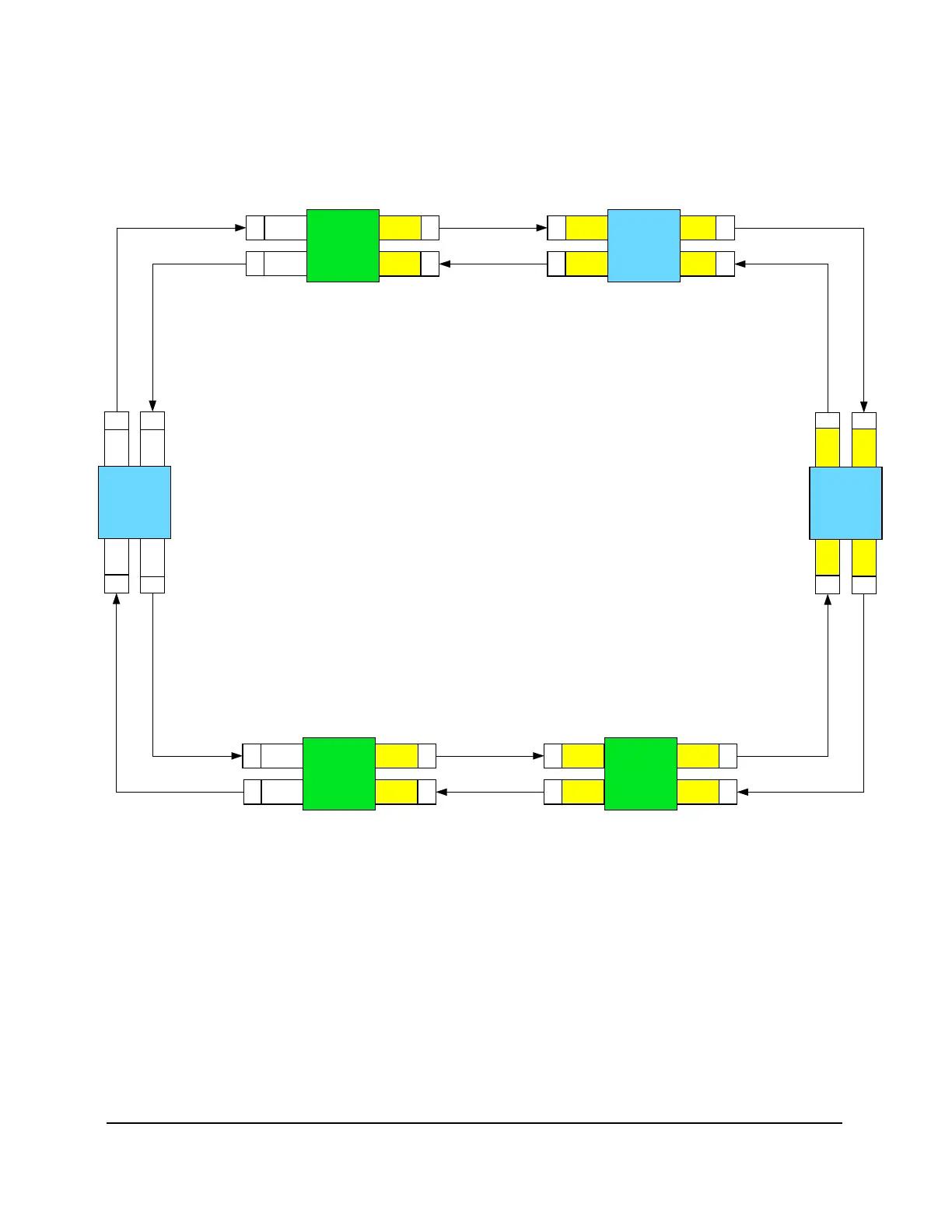
The figure below shows an example of another typical Z33/Z77 ring configuration with odd to even slots
connected in a clockwise direction. In this example, Site 2 has only WSS cards installed in a Z33 shelf. In
this shelf the WSS-402 cards must be installed in slots 1 and 2 to act as controller cards. The WSS cards in
the Z33 shelf at Site 3 are also installed in slots 1 and 2 to match the slots at Site 2.
LAD-8
Slot 16
R
X
T
X
Site 1
Z77
WSS
Slot 15
LAD-8
Slot 16
WSS
Slot 15
R
X
T
X
WSS
Slot 2
R
X
T
X
Site 2
Z33
WSS
Slot 1
WSS
Slot 2
WSS
Slot 1
R
X
T
X
LAD-8
Slot 15
R
X
T
X
Site 5
Z77
WSS
Slot 16
LAD-8
Slot 15
R
X
T
X
R
X
T
X
Site 4
Z77
WSS
Slot 16
R
X
T
X
WSS
Slot 2
R
X
T
X
Site 3
Z33
R
X
T
X
LAD-8
Slot 6
R
X
T
X
Site 6
Z33
LAD-8
Slot 5
LAD-8
Slot 6
LAD-8
Slot 5
R
X
T
X
WSS
Slot 16
WSS
Slot 15
WSS
Slot 15
WSS
Slot 16
WSS
Slot 2
WSS
Slot 1
WSS
Slot 1
Figure 113: Ring Configuration with WSS-402 Cards Only in a Node Site
Fiber Patches
Fiber patches on LAD and WSS cards should be connected from even card slots to even card slots and odd
card slots to odd card slots.
Fiber patches on multi-port line cards (for example, PME-412, PME-216i, DTM-8, MSE-1482, SFT-8, or
SFT-10G16) should be connected from even ports to even LAD and WSS slots and odd ports to odd LAD
and WSS slots.



 To Next Page