Cyan Z-Series Engineering and Planning Guide Release 5.0
Page 28 © 2013 Cyan, Inc. – All Rights Reserved. 700-0023-05-00 Rev. 1
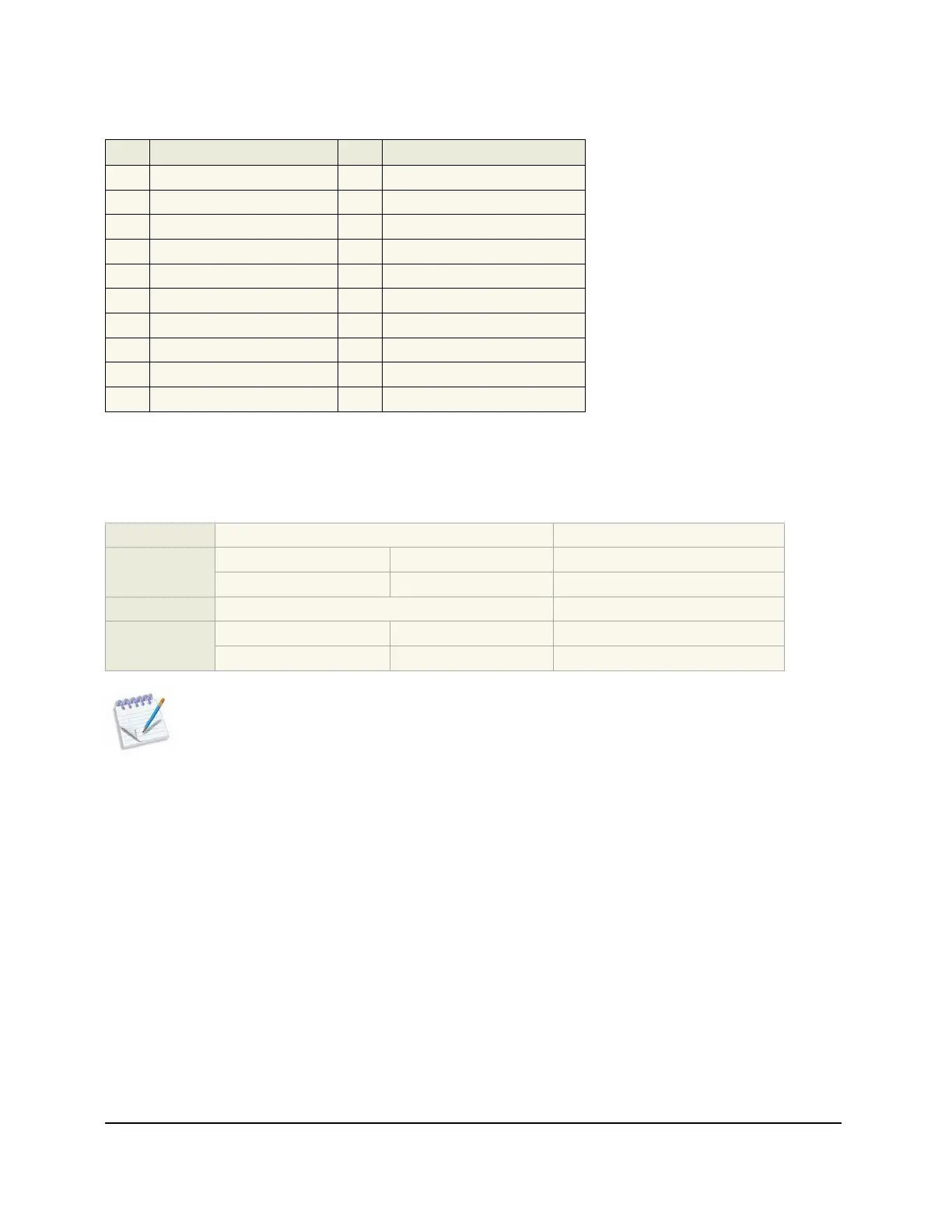
The following table shows the connector pinouts for the system and environmental alarms:
Pin Description Pin Description
1 CRIT_NO 1 IN1_+
2 CRIT_C 2 IN1_COM
3 MAJ_NO 3 IN2_+
4 MAJ_C 4 IN2_COM
5 MIN_NO 5 IN3_+
6 MIN_C 6 IN3_COM
7 FAIL_NC 7 IN4_+
8 FAIL_C 8 IN4_COM
9 OUT2_NO 9 OUT1_NO
10 OUT2_C 10 OUT1_C
For details on configuring environmental alarms, see the Cyan Z-Series Troubleshooting and Maintenance
Guide.
1.1.7 Z22 Shelf Power
Feeds:
2 1-A & 1-B
Voltage range:
-48V Configuration -40 to -60 Vdc Guaranteed Operation
+24V Configuration 18 to 30 Vdc Guaranteed Operation
Max voltage:
-/+100 Vdc Non-operational, no damage
Max current:
-48V Configuration 10 Amps
+24V Configuration 20 Amps
Note: Use Planet Design as a guideline based on the total configured system current draw.
You must size fuses according to NEC standards or local site practice.