ENGLISH
69
NOTE: The +19 [Vdc] power supplies to pins 11 and 18 and J5 (18-pole terminal board) can deliver a
maximum of 50 [mA].
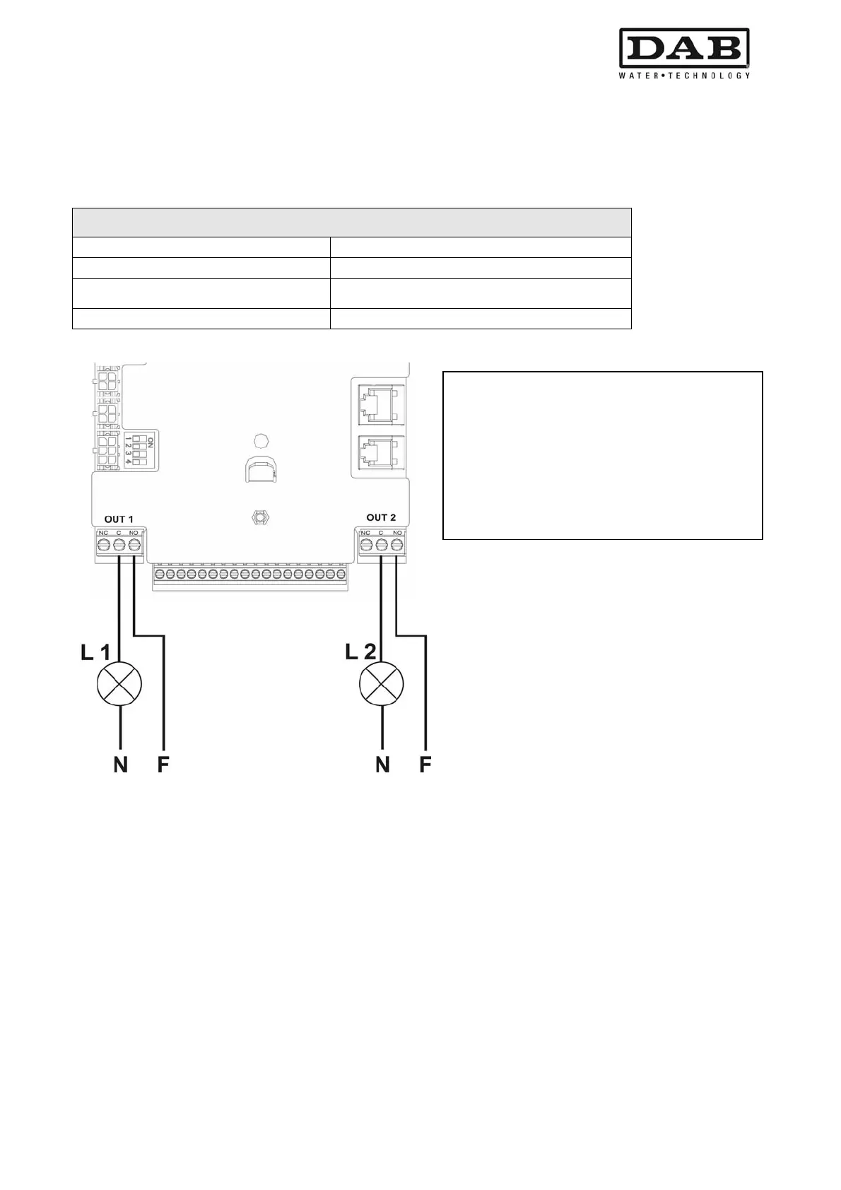
2.2.4.1 OUT 1 and OUT 2 output contact specifications:
The connections of the outputs listed below refer to the two 3-pole terminal boards J3 and J4 marked OUT1
and OUT 2, with a text below indicating the type of terminal contact.
Output contact specifications
Type of contact NO, NC, COM
Max. admissible voltage [V] 250
Max. admissible current [A]
5 -> resistive load
2,5 -> inductive load
Max. admissible cable section [mm²] 3,80
Table 5: Output contact specifications
Figure 7: Example of output connections
2.2.4.2 Photocoupled input contact specifications
The connections of the inputs listed below refer to the 18-pole terminal board J5, with numbering starting
from pin 1 from the left. The base of the terminal board also bears the text of the corresponding inputs.
- I 1: Pins 16 and 17
- I 2: Pins 15 and 16
- I 3: Pins 13 and 14
- I 4: Pins 12 and 13
The inputs can be activated in DC or AC (50-60 Hz). The following table shows the electrical specifications of
the inputs: Table 6.
With reference to the example in Figura 7 and
using the default settings (O1 = 2: contact NO;
O2 = 2; contact NO) the following is obtained:
L1 lights up when the pump is blocked
(e.g. "BL": water failure block).
L2 lights up when the pump is running
("GO").
 Loading...