ENGLISH
70
Input specifications
DC inputs [V]
AC inputs 50-60 Hz
[Vrms]
Minimum activation voltage [V] 8 6
Maximum deactivation voltage [V] 2 1,5
Maximum admissible voltage [V] 36 36
Current absorption at 12V [mA] 3,3 3,3
Max. admissible cable section [mm²] 2,13
N.B. Inputs can be controlled with both polarities (positive or negative with respective return to earth)
Table 6: Input specifications
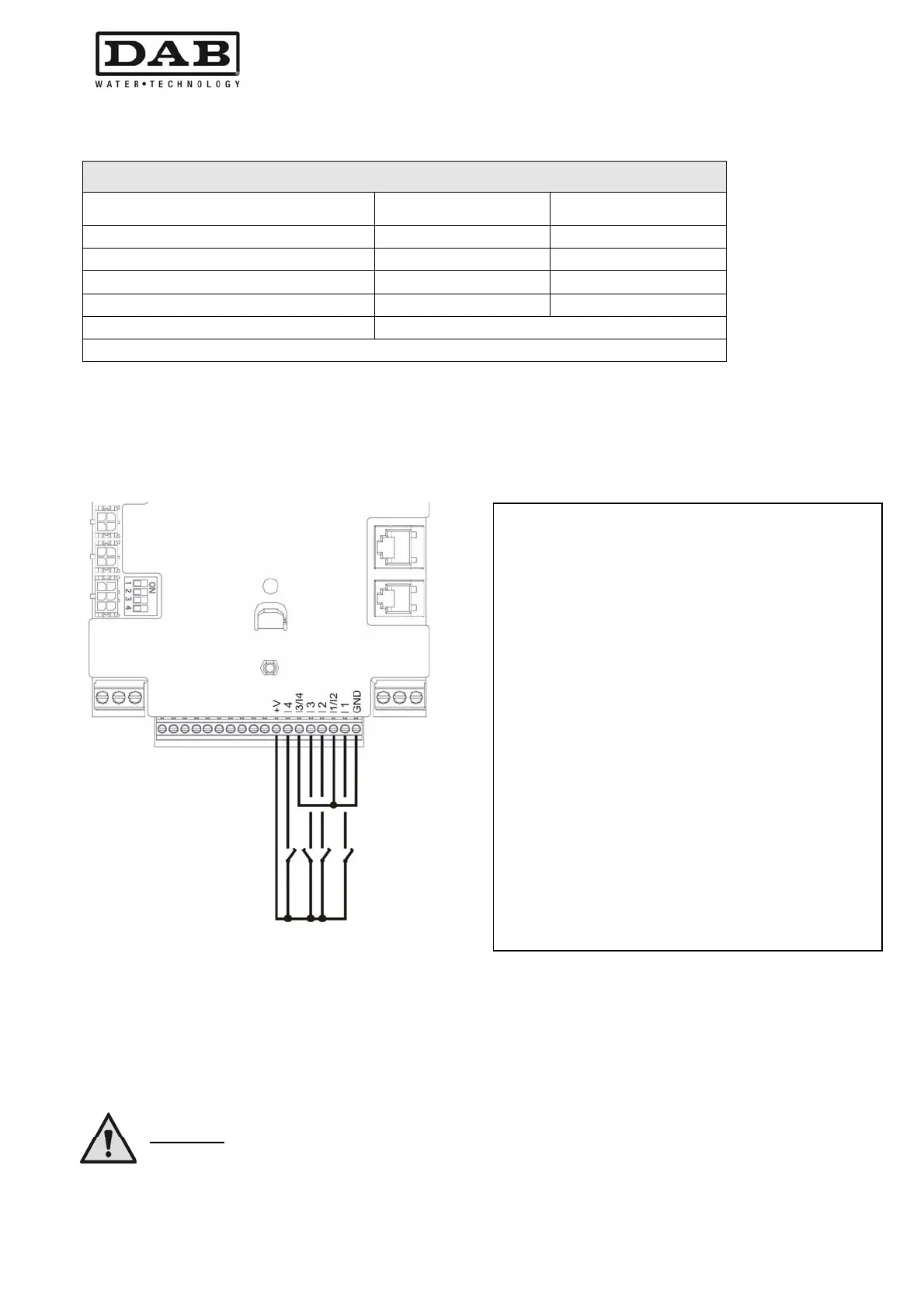
Figure 8 shows an example of input application.
Figure 8: Example of input connections
The example in Figure 8, refers to a connection with voltage-free contact, using the internal voltage to control
the inputs (obviously using only useful inputs).
If a voltage rather than a contact is available, this can still be used to control the inputs: in this case terminals
+V and GND are not used and the voltage source (complying with the specifications of Table 6) is connected
to the required input. If an external voltage is used to control the inputs, all the circuitry must be protected by
double insulation
.
CAUTION:
the pairs of inputs I1/I2 and I3/I4 have one pole in common for each pair.
With reference to the example in Figure 8 and using
the default input settings (I1 = 1; I2 = 3; I3 = 5;
I4=10) the following is obtained:
When the switch on I1 is turned off the
pump blocks and the signal "F1 is displayed"
(eg.. I1 connected to a float see section
6.6.13.2).
When the switch on I2 is turned off the set
pressure becomes "P2"
(see section 6.6.13.3)
When the switch on I3 is turned off the pump
blocks and the signal "F3 is displayed"
(see section 6.6.13.4 t).
When the switch on I4 is turned, passed time
T1, the pump is blocked and the signal "F4
is displayed"(see section 6.6.13.5).
 Loading...