ENGLISH
75
3.3 Structure of menu pages
On power-up, a number of presentation pages are displayed, with the name of the product and logo, then
moving on to the main menu. The name of each menu is always displayed at the top of the screen.
The main menu always displays the following items:
Status:
operating status (e.g. standby, go, Fault, input functions)
Frequency
: value in [Hz]
Pressure: value in [bar] or [psi] depending on the set unit of measurement.
If an event occurs, the following may be displayed:
Fault messages
Warning messages
Messages on functions associated with inputs
Special icons
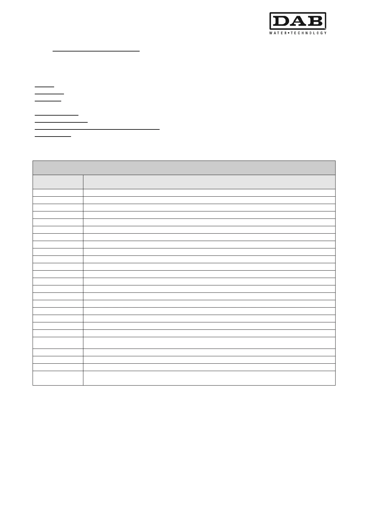
The error or status conditions visible in the main menu are listed in Table 10.
Table 10: Error status messages on main page
The other menu pages vary according to the associated functions, and are described below according to the
type of specification or setting. After entering any one of the menus, the lower section of the page always
shows a summary of the main operating parameters (operating status or possible fault status, applied
frequency and pressure).
This enables a constant overview of the main machine parameters.
Error and status conditions visible in the main menu
Identifier Description
GO Electric pump ON
SB Electric pump OFF
BL Block due to water failure
LP Block due to low power supply voltage
HP Block due to high internal power supply voltage
EC Block due to incorrect setting of rated current
OC Block due to current overload on electric pump motor
OF Block due to current overload on final stages of output
SC Block due to short circuit on output phases
OT Block due to overheating of final power stages
OB Block due to overheating of printed circuit
BP Block due to fault on pressure sensor
NC Pump not connected
F1 Float function status/alarm
F3 System disable function status/alarm
F4 Low pressure signal function status/alarm
P1 Operating status with auxiliary 1 pressure
P2 Operating status with auxiliary 2 pressure
P3 Operating status with auxiliary 3 pressure
P4 Operating status with auxiliary 4 pressure
Com. icon with
number
Operating status in multi inverter communication with specified address
Com. icon with E
Error status in communication of multi inverter system
E0...E16 Internal error 0...16
EE Writing and reading on EEprom of factory settings
WARN.
Low voltage
Warning due to power supply voltage failure
 Loading...