Xtium-CL MX4 User's Manual Contents • iii
Trigger Signal Validity 64
Supported Transfer Cycling Methods 64
OUTPUT LUT AVAILABILITY 65
METADATA: THEORY OF OPERATION 66
Metadata Data Structure 66
FLAT FIELD CORRECTION: THEORY OF OPERATION 67
Flat Field Correction Lists 67
Flat Field Correction Sets 68
Xtium-CL MX4 specific limitations 68
Programming the sets 68
XTIUM-CL MX4 SUPPORTED PARAMETERS 69
Camera Related Capabilities 69
Camera Related Parameters 70
VIC Related Parameters 75
ACQ Related Parameters 80
Transfer Related Capabilities 81
Transfer Related Parameters 82
General Outputs #1: Related Capabilities (GIO Module #0) 82
General Outputs #1: Related Parameters (GIO Module #0) 82
General Inputs #1: Related Capabilities (GIO Module #1) 83
General Inputs #1: Related Parameters (GIO Module #1) 83
Bidirectional General I/Os: Related Capabilities (GIO Module #2) 83
Bidirectional General I/Os: Related Parameters (GIO Module #2) 83
SAPERA SERVERS & RESOURCES 84
SERVERS AND RESOURCES 84
WINDOWS EMBEDDED 7 INSTALLATION 85
TECHNICAL SPECIFICATIONS 86
XTIUM-CL MX4 BOARD SPECIFICATIONS 86
HOST SYSTEM REQUIREMENTS 88
EMI CERTIFICATIONS 89
CONNECTOR AND SWITCH LOCATIONS 90
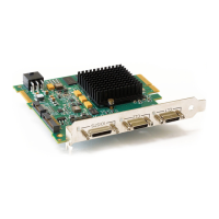
Xtium-CL MX4 Board Layout Drawing 90
Connector / LED Description List 90
CONNECTOR AND SWITCH SPECIFICATIONS 91
Xtium-CL MX4 End Bracket Detail 91
Status LED Functional Description 92
J3: Camera Link Connector 1 93
J2: Camera Link Connector 2 94
Camera Link Camera Control Signal Overview 95
J1: External Signals Connector (Female DH60-27P) 96
J4: Internal I/O Signals Connector (26-pin SHF-113-01-L-D-RA) 96
Xtium-CL MX4 rev. A2 96
Xtium-CL MX4 rev. A1 97
Note 1: General Inputs / External Trigger Inputs Specifications 98
Block Diagram: Connecting External Drivers to General Inputs on J1 or J4 100
External Driver Electrical Requirements 101
Note 2: General Outputs /Strobe Output Specifications 102
Block Diagram: Connecting External Receivers to the General Outputs 103
External Receiver Electrical Requirements 104
Note 3: RS-422 Shaft Encoder Input Specifications 105
Note 3.1: Interfacing to an RS-422 Driver Output 106
Note 3.2: Interfacing to a TTL (also called Push-Pull) Output 107
Note 3.3: Interfacing to a Line Driver (also called Open Emitter) Output 107
Note 3.4: Interfacing to an Open Collector Output 108
J5: Multi-Board Sync / Bi-directional General I/Os 108
Hardware Preparation 108