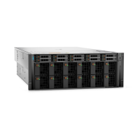
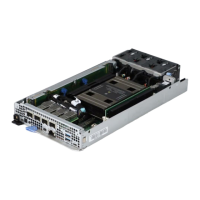
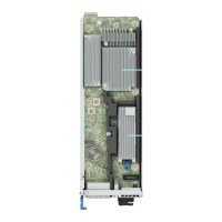
Figure 168. Installing the H100/H800 baseboard captive screws
3. When installing a new GPU and heatsink module, carefully remove the bottom shipping plastic covers that protect the
pinfield, and visually inspect the pinfield to ensure that no pins are bent or damaged before installing the module.
NOTE:
If any pin fields on the module or the GPU baseboard appear damaged, DO NOT install the module. Call tech
support to determine the best course of action.
4. Align and insert the GPU and heatsink module on the GPU socket.
NOTE: H100/H800 GPU and heatsink module is one part and is installed together.
5. Using Torx 15 screwdriver, tighten the four screws securing the GPU and heatsink module. Assembly order: 1, 2, 3, 4.
NOTE:
When installing screws into the GPU and heatsink module, ensure that the final torque value is 5.2 ± 4% lbf-in or
0.6 ± 4% N-m.
NOTE: There are eight GPU and heatsink module on the GPU baseboard. Repeat steps 4 and 5 to install remaining GPU
and heatsink module.
NOTE: After all GPU and heatsink modules are installed, place the plastic protective pin field covers unto the old GPU
baseboard locations to protect those pins fields during return shipment.
186 Installing and removing system components

 Loading...

