27
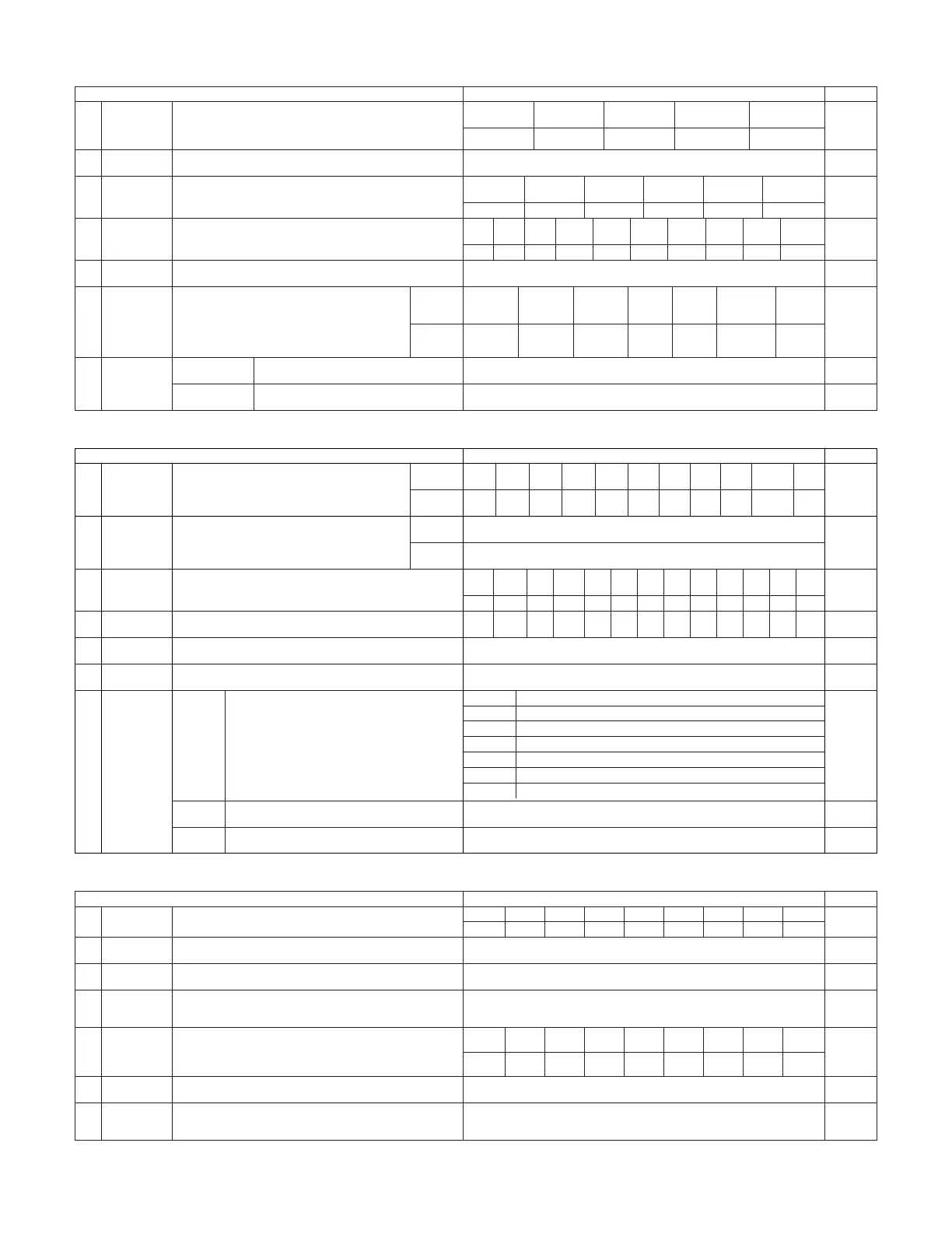
3. Audio Input Setup
Audio Input Setup Default settings Page
58, 59
Digital In
Assign
This assigns the digital input jacks for the different input
sources.
Input
source
Digital
Inputs
CD DVD VDP TV DBS VCR-1 VCR-2
COAX 1 COAX 2 COAX 3 COAX 4 COAX 5 OPT 1
OPT 2
1
CDR/TAPE
OPT 5
VCR-3 VCR-4
OPT 3 OPT 4
V.AUX
OPT 6
2
EXT.IN Setup Set the Ext.In terminal playback method.
EXT.IN-1
Setup
EXT.IN-2
Setup
Mode = DSP, Surr.B = NOT USED, S.Back = NOT USED,
SW Level = +15 dB, Input ATT. = OFF
Mode = DSP, SW Level = +15 dB, Input ATT. = OFF
62
Input Function
Lev.
The playback level is corrected individually for the different input
sources.
TUNER PHONO CD
CDR/
TAPE
DVD VDP TV
0 dB 0 dB 0 dB 0 dB 0 dB 0 dB 0 dB
3
VCR-2
0 dB
DBS VCR-1
0 dB 0 dB
VCR-3
0 dB
VCR-4
0 dB
V.AUX
0 dB
4
Function
Rename
The names of the different input source can be changed as desired
and displayed on the display.
63, 64
5
IEEE1394
Assign
The connected IEEE1394 device can be automatically identified to
assign the input source.
–65
6
IEEE1394
Auto Func.
Set the function for associating playback of the connected IEEE1394
device on or off.
Auto Function = OFF 66
7
Tuner Presets
FM stations are received automatically and stored in the
memory.
A1 ~ A8
B1 ~B8
C1 ~C8
D1 ~D8
E1 ~E8
87.5/89.1/98.1/107.9/90.1/90.1/90.1/90.1 MHz
520/600/1000/1400/1500/1710 kHz, 90.1/90.1 MHz
90.1 MHz
90.1 MHz
90.1 MHz
Auto
Preset
Memory
F1 ~F8
G1 ~G8
90.1 MHz
90.1 MHz
Preset channels that are not used often can be skipped.
Preset
Skip
The preset channels can be given the names you want.
Preset
Name
67
All preset channels = OFF 68
– 69, 70
60, 61
TUNER PHONO CD
CDR/
TAPE
DVD VDP TV
VCR-2DBS VCR-1 VCR-3 VCR-4 V.AUX
2. Speaker Setup
Speaker Setup Default settings
1
3
Speaker
Configuration
Channel Level
Input the combination of speakers in your system and their
corresponding sizes (SMALL for regular speakers, LARGE for full-
size, full-range) to automatically set the composition of the signals
output from the speakers and the frequency response.
This adjusts the volume of the signals output from the speakers and
subwoofer for the different channels in order to obtain optimum
effects.
Front Sp.
Small
Center Sp.
Surround Sp.
A / B
Subwoofer
Small SmallYes
Front L & R Center
Surround
L & R (A)
Subwoofer
12 ft (3.6 m) 12 ft (3.6 m) 10 ft (3.0 m)12 ft (3.6 m)
Front L Front R Center
Surround
R (A)
Surround
R (B)
Subwoofer
0 dB 0 dB 0 dB 0 dB
0 dB
0 dB
Surround Back
Sp.
Small / 2spkrs
4
Delay Time
This parameter is for optimizing the timing with which the audio
signals are produced from the speakers and subwoofer according to
the listening position.
Surround
L & R (B)
10 ft (3.0 m)
Surround
L (B)
0 dB
Surround
L (A)
0 dB
Crossover
Frequency
Set the frequency (Hz) below which the bass sound of the various
speakers is to be output from the subwoofer.
5
FIXED —THX—
Page
46, 47
2
Subwoofer
Setup
This selects the subwoofer for playing deep bass signals. LFE —THX— 48
49, 50
51, 52
53, 54
Surround
Speaker Setup
Use this function when using multiple surround speaker
combinations for more ideal surround sound. Once the
combinations of surround speakers to be used for the
different surround modes are preset, the surround
speakers are selected automatically according to the
surround mode.
Surround
mode
Surround
speaker
THX/DOLBY/
DTS
CINEMA
THX/DOLBY/
DTS
MUSIC
WIDE
SCREEN
9 CH
STEREO
DSP
SIMULATION
MULTI CH
MODE
A A A A+B A+B A+B A
6
THX/DOLBY
GAME
55
7
THX Audio
Setup
When using a THX Ultra2 compatible subwoofer,
set the subwoofer’s frequency response.
THX Ultra2 Subwoofer = NO
Boundary Gain
compensation
Surround Back
Speaker Position
When using two surround back speakers, set
the distance of the two speakers.
The Distance Between SBL/SBR = 0 ft to 1 ft (0 m to 0.3 m)
56
Surround
Back
10 ft (3.0 m)
Surround
Back R
0 dB
Surround
Back L
0 dB
4. Video Setup
Video Setup Default settings
1
3
Component In
Assign
HDMI/DVI In
Assign
This assigns the color difference (component) video input jacks for
the different input sources.
The HDMI or DVI input terminals are assigned for the different input
sources.
Select HDMI or DVI for the monitor output terminal.
Select the HDMI audio signal playback method.
DVD VDP TV
5
Video Scaler
Make the settings related to video output (resolution and aspect rate
conversion).
Audio Delay Set the audio delay timing to synchronize the sound and video.
6
0 ms
Page
71, 72
2
Video Convert
Mode
Set the input signal to be output from the monitor output terminal. AUTO 72, 73
73, 74
75, 76
76, 77
On Screen
Display
This sets whether or not to display the on-screen display that
appears on the monitor screen when the controls on the remote
control unit or main unit are operated.
7
Function/Mode = ON, Master Volume = ON, Mode = Mode 1 77, 78
DBS VCR-1 VCR-2 VCR-3 VCR-4 V.AUX
1-RCA 2-RCA 3-RCA 4-RCA 5-RCA 6-BNC NONE NONE NONE
Aspect = FULL, Resolution = 480i / 576i
DVD VDP TV
DBS VCR-1 VCR-2 VCR-3 VCR-4 V.AUX
NONE NONE NONE NONE NONE NONE NONE NONE NONE
4
3D Y/C
Separation
This setting sets the action detection sensitivity of the 3-dimensional
Y/C separation at the time of the video signal up-conversion to S-
Video.
74Motion Detection = MID
57
 Loading...