1 Introduction
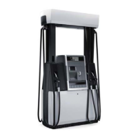
This manual contains detailed service information for Wayne Helix™ fuel dispensers. This
manual applies to Helix 1000, 2000, 4000 (narrow body), 5000 (wide body) and 6000 (C-style)
model series. The manual should be used for troubleshooting and repair purposes by Wayne
certified technicians only.
This is a global service manual used by technicians around the world servicing Helix dispensers.
"NA" in this manual refers to parts or procedures used specifically in North America. "IEC" in
this manual refers to parts or procedures used specifically in Europe and in countries adhering
to IEC and ATEX standards.
1.1 Features
Some of the features of Helix dispensers are listed below:
•
Most current circuit design and functionality, with expansion capabilities for various types of
displays and future options
•
New two-piece bezel
•
Many of the outside components and bezel parts snap in place and do not require hardware
•
Improved serviceability of hydraulic components — valves, meters, and outlet castings. Using
the new tube removal tool, there is no longer a need to use ladders when replacing product
tubes
•
New filter/strainer casting and attached funnel to reduce fuel spills when changing filters
•
Newly designed dual vapor barrier with a 1-1/2 inch space between the two barriers eliminates
need for lock nuts above and below the barrier. This makes changing valve coil/conduits
much easier. WIP cables and nozzle switch wires are no longer in a potted fitting and can be
replaced individually
•
New power on/off switch located by the iGEM board shuts down power in the dispenser
•
Easily replaceable nozzle boots
•
Incorporates use of USB printer
The following sections in this manual give details on the new hydraulic and electronic components
used in Helix dispensers. The figures on the following pages show how to gain access to the
inside of the dispenser for service.
WM048523 Rev 08 01/2019 7
1 Introduction

 Loading...