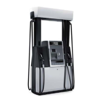
15 Helix 6000 DEF, Extra Narrow Model Dispensers - IEC
Components in the Helix 6000 DEF dispenser hydraulics cabinet are shown in Figures 15.1
through 15.5. Components in the electronics head are shown in Figures 15.7 and 15.8.
The ATC (Temp Comp) module used in DEF dispensers is not used for ATC as in other Helix
dispensers. In DEF dispensers, the temperature module is used for the probes that monitor the
temperature in the tanks, hose cabinet, and hydraulics cabinet. The probe data is sent from the
ATC module through the temperature ISB module and then to the TTL/CAN converter circuits
on the Heater Control board. From here, iGEM monitors the temperatures from 3 (or 4) probes
via the CAN bus and tells the heater control board to turn the heater on or off in order to keep
the fluid in the tanks at a temperature that is above freezing. The DEF fluid will crystallize at -
7°C and freeze at -11°C.
Temperature probe #1 is located in the hose cabinet to check the ambient temperature. Probe
#2 is located in the hydraulics cabinet. Probe #3 is in fluid tank A, and for dual sided dispensers,
probe #4 is in fluid tank B.
The circulation pump will run during cold weather, by default when the temperature is below -4
C but this can be changed in iGEM function F71. It will have a hysteresis of 5 degrees, so the
circulation motor will by default stop when the temperature is above 1 C.
When a fuelling is started, the circulation pump will stop in order to keep heated DEF liquid in
the tanks. The circulation motor will start again when the fuelling has ended.
During warmer weather, when there is no risk of the DEF freezing, the motor will by default run
5 minutes once every 24 hour to prevent DEF liquid to be standing in the tanks for too long. The
times can be adjusted by iGEM function F71.
The circulation pump pumps the heated DEF through the tanks and to the hose adapter connection
near the solenoid valve. From this connection the DEF is pumped through an inner, coaxial hose
out to the bottom of the nozzle. At the nozzle, the DEF fluid flows out to the outer house (the
regular hose) and circulates back to the pump. Figure 15.3 shows the fluid flow direction through
the pump on side B, and Figure 15.5 shows the fluid flow direction through the pump on side A.
WM048523 Rev 08 01/2019 241
15 Helix 6000 DEF, Extra Narrow Model Dispensers - IEC

 Loading...