Chapter 4: Programming the Rhino2
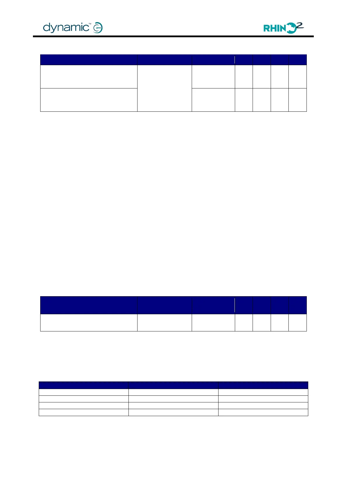
4.4.10.2 Pin 3/11 Function
None
Brake Light
Reverse Light
Beeper
Status
Power Status
These parameters set the function of Pin 3 and pin 11 on the tiller connector.
Pin 3 and pin 11 are both capable of sinking 500 mA. To use the outputs, connect a 24V
beeper, lamp, or Status LED (with resistor) between B+ and pin 3 or pin 11.
None - The output is not used.
Brake Light - The output pin drives a 24V brake light. The brake light is on when the
scooter decelerates in either the forward or reverse direction. Connect the
light between B+ and the pin that has 'Brake Light' selected.
Reverse Light - The output pin drives a 24V brake light. The brake light flashes at 0.5 Hz
when the scooter drives in reverse. Connect the light between B+ and the
pin that has 'Reverse Light' selected.
Beeper - The output pin drives a 24V beeper. Connect the beeper between B+ and
the pin that has 'Beeper' selected. To activate any beeper sounds,
set Enable Beeper (4.4.1.4) to 'Yes'. Other beeper options can be selected
with Flash Code Beeper (4.4.1.5), Sleep Beeper (4.4.1.6), Motion Beeper
(4.4.1.7), Deep Discharge Beeper (4.4.1.10), Reversing Beeper (4.4.1.8) ,
and Beeper Timing (4.4.1.9).
Note that the Reversing Beeper parameter does not exist in the Wizard as the Motion Beeper
parameter can be used to switch on the beeper for reversing.
When using the HHP to program, use both the Motion Beeper and the Reversing Beeper
parameters, as set out in the table below.