EasyManuals Logo

Dynamic RHINO2 User Manual

Dynamic RHINO2
128 pages
To Next Page IconTo Next Page
To Previous Page IconTo Previous Page
Page #31 background imageLoading...
Page #31 background image
Chapter 3: Installation and Testing
31
3.9 Tiller Connector
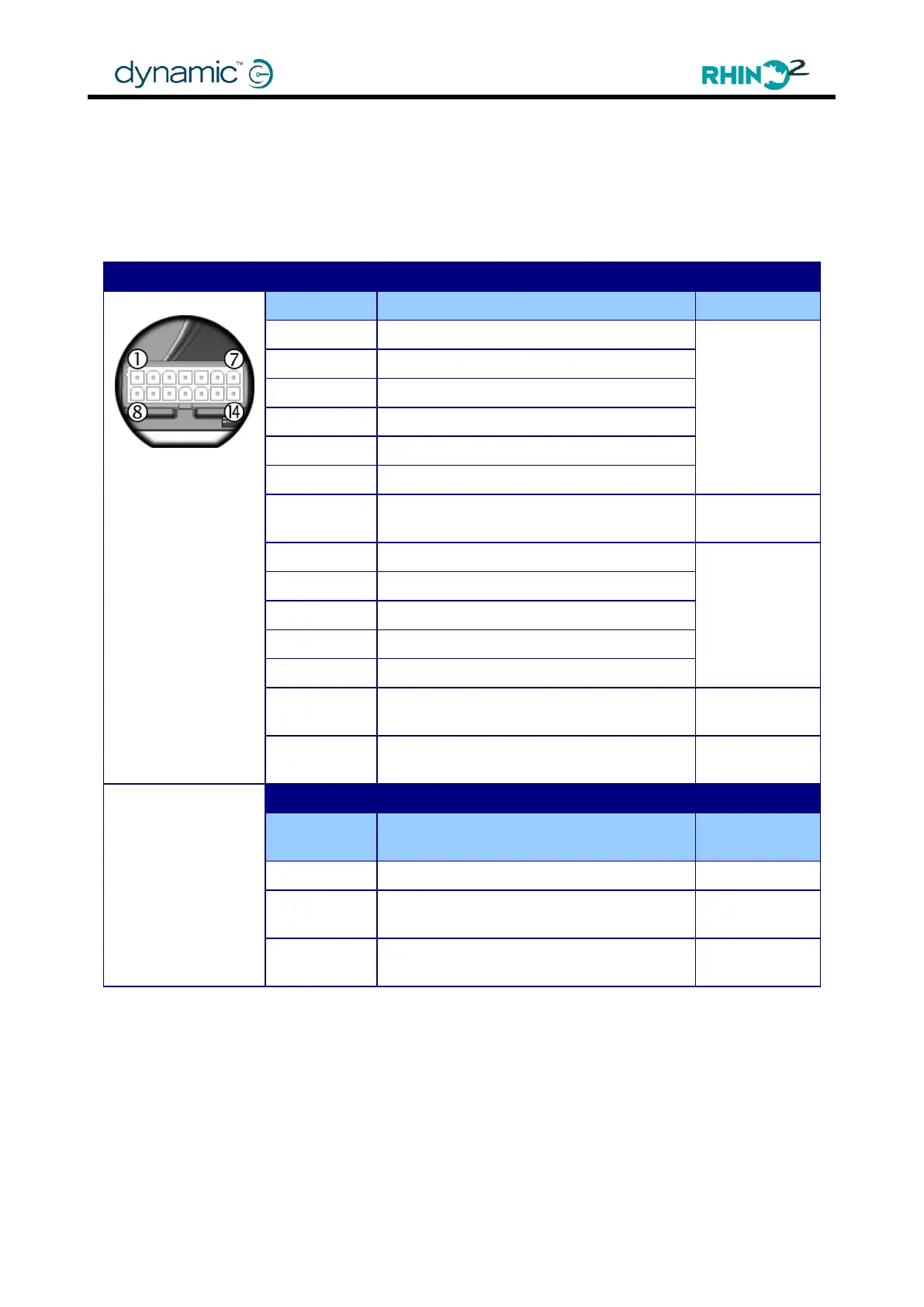
The tiller connector provides all the connections necessary to power and control all the
functions contained in the tiller head. This connector also supports the new Multi-function pins
that can be configured for alternative functionality depending on application requirements.
Where the Multi-function pins are listed below, the bold text indicates the recommended
default functions.
Tiller Connections
Pin
Function
Wire Gauge
1
Throttle Wiper (TW)
0.5mm²
(20AWG)
2
Throttle Positive (T+)
3
Multi-function Output (Beeper)
4
Multi-function Input (Profile 2)
5
Key Switch (KS)
6
Multi-function Input (Slow)
7
Battery Positive (B+)
1.0mm²
(18AWG)
8
Throttle Negative (T-)
0.5mm²
(20AWG)
9
Speed Limit Pot (SLP)
10
Multi-function Output (Status Low)
11
Multi-function Output (none)
12
Multi-function Input (Reverse Drive)
13
Battery Negative (B-)
1.0mm²
(18AWG)
14
Multi-function Input (Charger Inhibit)
0.5mm²
(20AWG)
Mating Connector Part Numbers
Dynamic
Part #
Part Description
Supplier Part #
GCN0887
Molex „Mini-Fit Jr‟ 14-socket housing
39-01-2145
GCN0776
Molex „Mini-Fit Jr‟ Receptacles
16AWG (0.8 1.3mm² wire)
39-00-0212
GCN0771
Molex „Mini-Fit Jr‟ Receptacles
18-24AWG (0.2 0.8mm² wire)
39-00-0039

Table of Contents

Other manuals for Dynamic RHINO2

Questions and Answers:

Question and Answer IconNeed help?

Do you have a question about the Dynamic RHINO2 and is the answer not in the manual?

Dynamic RHINO2 Specifications

General IconGeneral
BrandDynamic
ModelRHINO2
CategoryController
LanguageEnglish

Related product manuals