Chapter 3: Installation and Testing
3.5.2 Motor Testing
The RHINO2 has 4 different modes for testing the motor circuitry: All, Open, Short and None.
These are configured in the Wizard with the Motor Testing parameter (4.4.5.12)
Warning:
It is highly recommended that motor testing is not turned off.
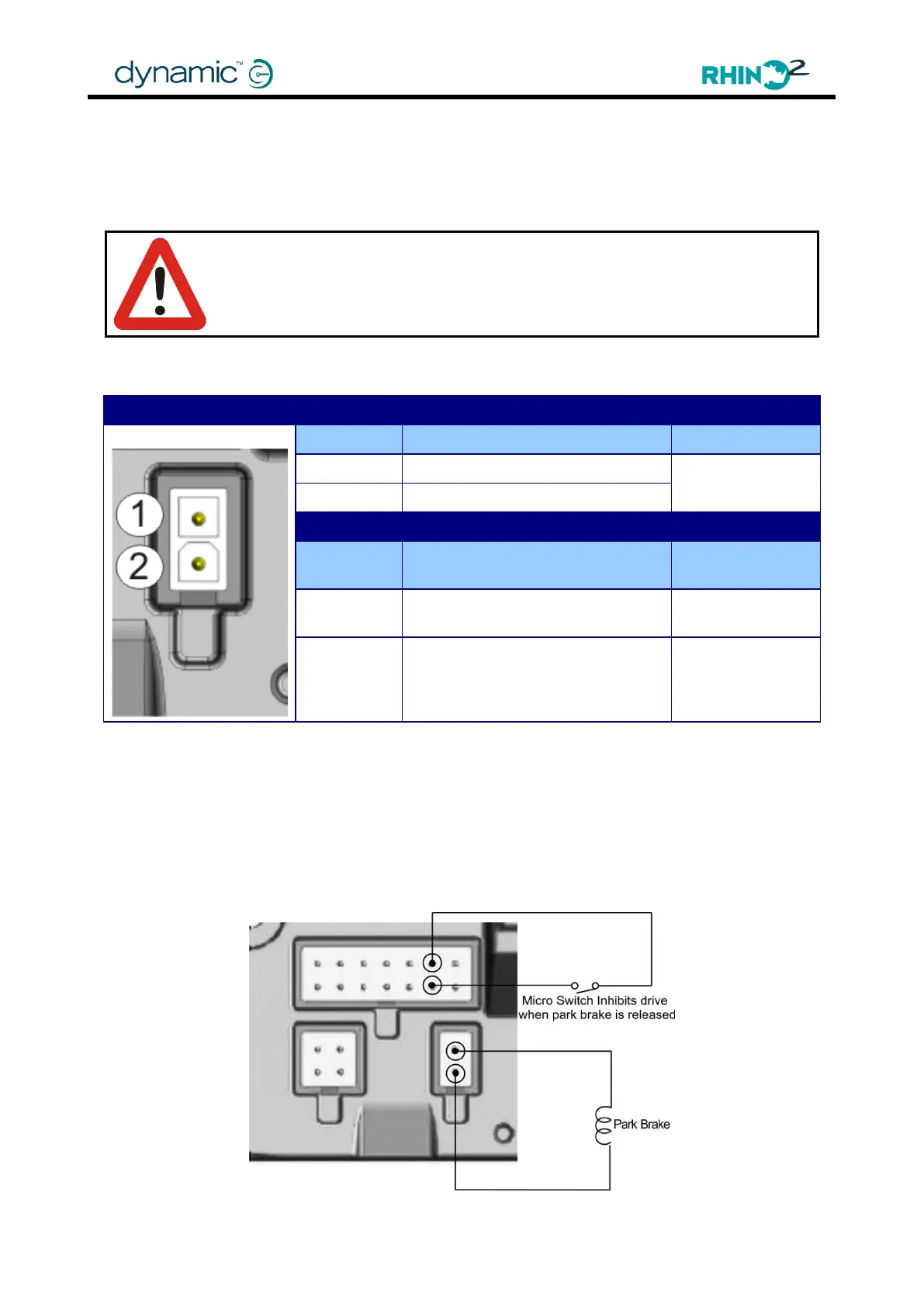
3.6 Park Brake Connections
Mating Connector Part Numbers
Molex „Mini-Fit Jr‟ 2-socket
housing
Molex „Mini-Fit Jr‟ Receptacles
18-24AWG
The RHINO2 supports a 24V park brake that is connected to the park brake connector.
A manual park brake release lever can be fitted so the scooter can be pushed when the
controller is turned off. To meet ISO requirements, if a manual park brake release lever is
fitted, a micro-switch should be connected in such a way that it inhibits driving when the
park brake is released.
For example, wire a micro-switch to any Multi-function input that is configured to inhibit
driving and mechanically couple this switch to the park brake release lever.
Recommended Park Brake Wiring using a mechanical release lever