Chapter 3: Installation and Testing
3.11.1.1 Active States
If a pin is in its active state, the corresponding function will be executed.
The input pins can be set to the following active states:
Low - Input is active when pulled down, inactive when open or pulled up
High - Input is active when pulled up, inactive when open or pulled down
Open - Input is active when open, inactive when pulled up or pulled down
Low or High - Input is active when pulled down or pulled up, inactive when open
Low or Open - Input is active when pulled down or open, inactive when pulled up
High or Open - Input is active when pulled up or open, inactive when pulled down
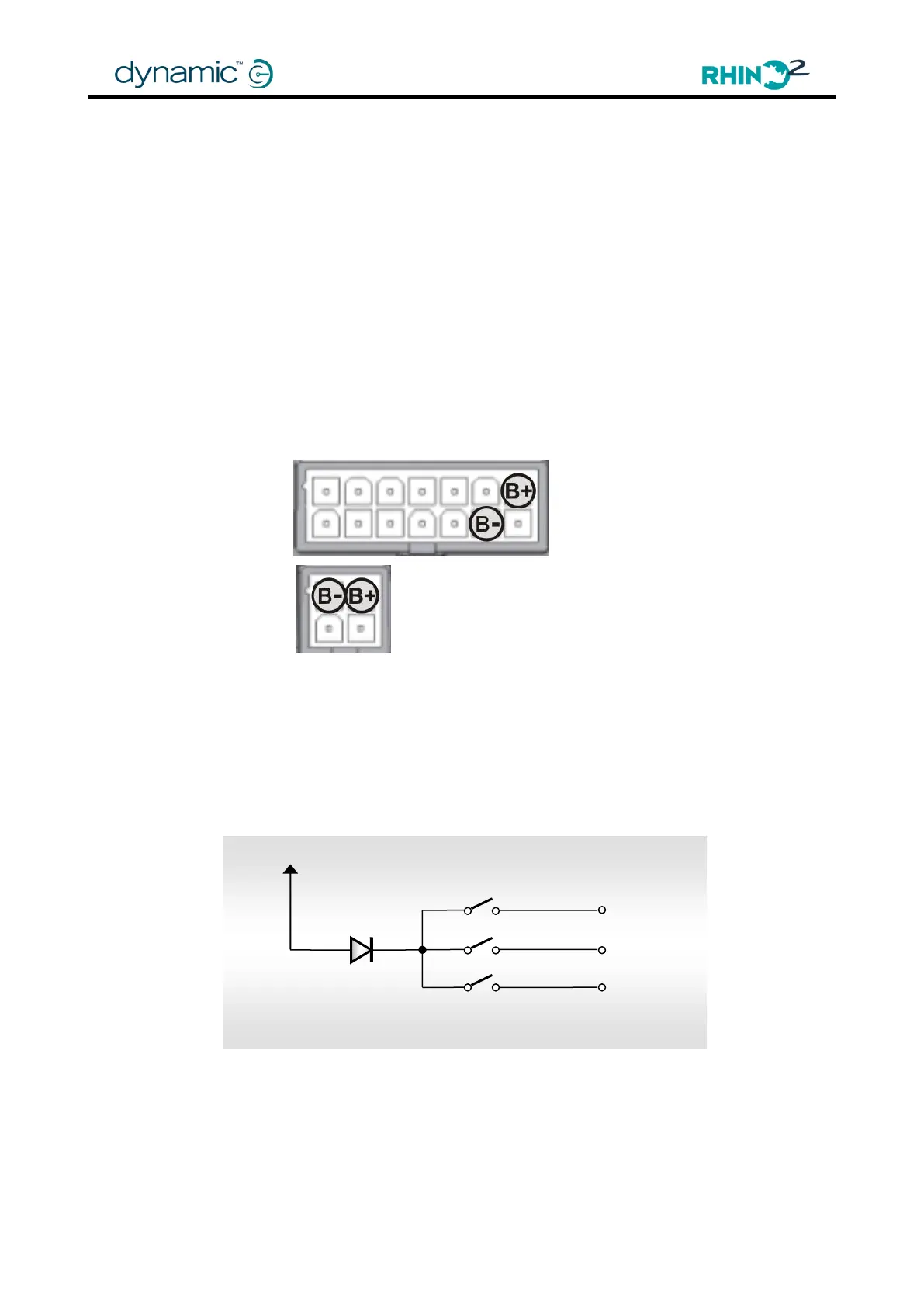
To pull up an input, connect it to B+. To pull down an input, connect it to B-.
If a multi function input switch is connected to B+, put a diode in series for increased
reliability. If multiple switches are connected to B+, it is not necessary to add a diode for
each of them. One diode for all multi function input switches combined is enough.
Insert the diode as close to the switches as possible.
Put a diode in series if switches are connected to B+