Chapter 3: Installation and Testing
3.11 Multi-function Pins
The Multi-function Pins maximise flexibility in both scooter design and installation. Allowing the
ability to be configured as one of multiple functions, scooter variations typically implemented
through wiring changes can now be implemented through programming.
The RHINO2 offers both Multi-function Input and Output pins.
3.11.1 Multi-function Inputs
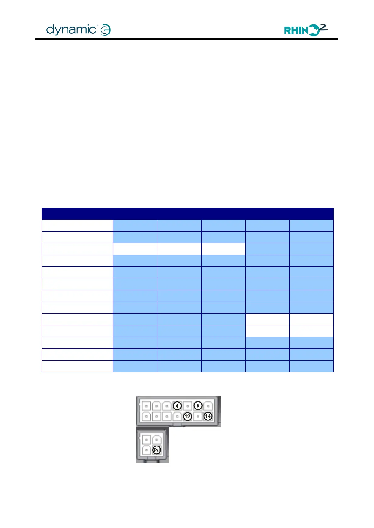
The Multi-function Inputs are available on pin 4, 6, 12 and 14 of the Tiller Connector and on the
Programming/Inhibit (P/I) pin of the programming connector. These inputs are activated by
external circuits. Each input pin can be set to operate a specific function (see table below).
Most functions are fully configurable as to the circuit state in which they are active (or
operating), as well as the ability to become latched (where the controller must be turned off
and then on again to cancel the function). In addition, the speed to which a Slow input
decelerates is fully customizable.
The table below shows the supported functionality for each input pin. The specific
functionality of each input will be explained in a further section.
For an extensive description of each function, see Multi-function Inputs Configuration (4.4.9).
Multi-function Input Pins