Chapter 4: Programming the Rhino2
4.4.2.11 Speed Limit Pot
Yes - The dedicated Speed Limit Pot input (pin 9) is used to limit the speed of the scooter.
Use this setting with a 100 kΩ speed pot that is connected IN PARALLEL with the
throttle, between 'Throttle Positive' (pin 2) and 'Throttle Negative' (pin 8), and that
has its wiper connected to pin 9 (speed limit pot input).
No - The Speed Limit Pot input (pin 9) is ignored.
Use this setting with a 25 kΩ speed pot that is connected IN SERIES with the throttle,
and that is connected to pin 1 (throttle wiper input).
For schematics and the use of ISO resistors, see Speed Limit Pot Connections (3.10.6).
Note:
If Speed Limit Pot is set to 'Yes' when no speed pot is connected to pin 9 (when the
speed pot is wired in series with the throttle instead of in parallel), the RHINO2 will
read pin 9 as if the speed pot is at its lowest setting, and will always limit the speed
of the scooter to the lowest forward and reverse speeds.
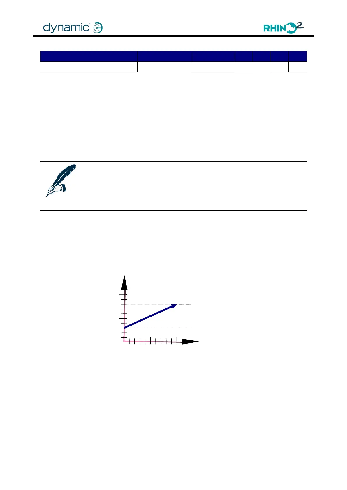
If the voltage at pin 9 is the same as Throttle Positive (T+), the maximum speed of the scooter
at 100% throttle deflection is not limited and is as set by the Maximum Forward Speed
(4.4.3.1) and Maximum Reverse Speed (4.4.3.4) parameters.
If the voltage at pin 9 is the same as Throttle Negative (T-), the maximum speed of the
scooter at 100% throttle deflection is scaled down to Minimum Forward Speed (4.4.3.7) and
Minimum Reverse Speed (4.4.3.8).
The throttle output is scaled down, not limited, so the throttle does not have a dead band
when the speed pot is at a low setting.
Maximum FWD Speed
Maximum REV Speed
Lowest FWD Speed
Lowest REV Speed