Chapter 3: Installation and Testing
3.10.4 Two throttle wipers - mirrored
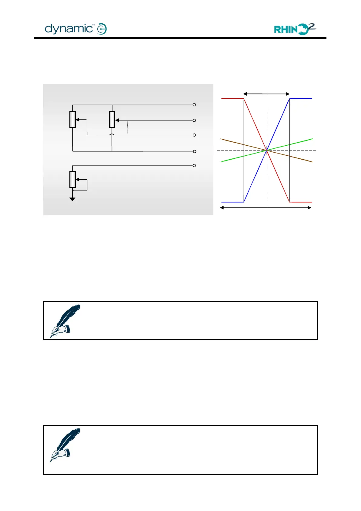
The RHINO2 supports the use of a 2x 10kΩ dual gang throttle with 2 linear wiper signals that are
each other's opposite. The throttle can either be a short travel or long travel variant.
To use this option, set the Throttle Input parameter (4.4.2.2) to 'Dual' and select the correct
throttle type with the Throttle Type parameter (4.4.2.1).
For a speed limit pot in series with the throttle wiper signals, insert a dual-gang speed limit pot
in series, and connect both pots to the 2 throttle wiper signals.
For a speed limit pot in parallel with the throttle, it is not possible to use the dedicated Speed
Limit Pot input (pin 9), because it is already used for the 2
nd
wiper input. To use a speed limit
pot in parallel with the throttle, connect the wiper to pin 4 (or pin 6, or pin 12) instead of pin 9,
and set Pin 4 Function (4.4.9.1) (or Pin 6 Function, or Pin 12 Function) to 'SRW'. See Speed Limit
Pot Connections (3.10.6.2) for more details.
Note:
If the throttle potentiometer is powered externally (not by T+ and T-),
take care to avoid ground shift. Ground shift will result in a throttle fault.
3.10.5 Throttle Calibration
For correct throttle operation, the electrical range of the throttle must be calibrated by
correctly setting Swap Throttle Direction (4.4.1.3), Throttle Neutral Offset (4.4.2.3), Minimum
Throttle Voltage & Maximum Throttle Voltage (4.4.2.8), Throttle Dead-band (4.4.2.6) and
Throttle Full Scale Deflection (4.4.2.4).
The HHP hand held programmer can calibrate the throttle automatically. It is recommended
to use the automatic process, especially for the Dual Decode circuits.
See Throttle calibration (4.1.1.3) in the programming section for details.
Note:
To calibrate the throttle with the Wizard PC-based programmer,
use the HHP emulator mode:
Tools -> Plug-ins -> HHP Emulation
10 kΩ log
speed limit
pot
Mirror