Chapter 3: Installation and Testing
3.5 Motor Connections
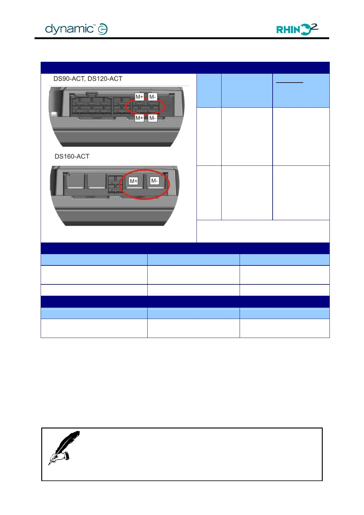
Note: Images shown are for the –ACT units. Position of motor
terminals for non –ACT units are identical.
Minimum Wire
Gauge
(see notes
below)
DS90: 2 x 3mm
2
(
2x12AWG)
DS120: 2 x 3mm
2
(
2x12AWG)
DS160: 2 x 5mm
2
(2x10AWG)
DS90: 2 x 3mm
2
(
2x12AWG)
DS120: 2 x 3mm
2
(
2x12AWG)
DS160: 2 x 5mm
2
(2x10AWG)
Mating Connector Part Numbers DS90, DS90-ACT, DS120, DS120-ACT
4W Housing 250 Series Plug
V0
Mating Connector Part Numbers DS160, DS160-ACT
Crimp terminal M5 ring
yellow 10-12AWG
The wire gauge recommendations above are the MINIMUM gauge and are generally
suitable for runs up to 400mm. Longer runs will require heavier wire – typically an extra
1.0mm
2
for each additional 200mm run length. The heavier the wire, the better driving
performance will be. In particular the length and gauge of wire affects the wire
resistance and hence the optimum Load Compensation setting.
Make sure that the Load Compensation parameter (4.4.5.5) is tuned to match the
scooter wiring for best driving performance.
These notes are in addition to the General Wiring Recommendations as described in
Section 3.3.1.
The motor polarity can be swapped with the Motor Reverse parameter (4.4.5.4).
Note:
The torque settings for the DS160, and DS160-ACT motor terminals should be between
4.5Nm and 5.5Nm.
For DS90, DS90-ACT, DS120, and DS120-ACT units, it is essential that all four motor
terminals are used.