Chapter 3: Installation and Testing
3.10.9 Key Switch Input
Pin 5 of the tiller connector provides the key switch power circuit. A high quality key switch
(>50,000 operations) should be used. Up to 2 status LEDs (up to 10mA each) may be wired in
line with this output as an alternative to using one of the Status output pins.
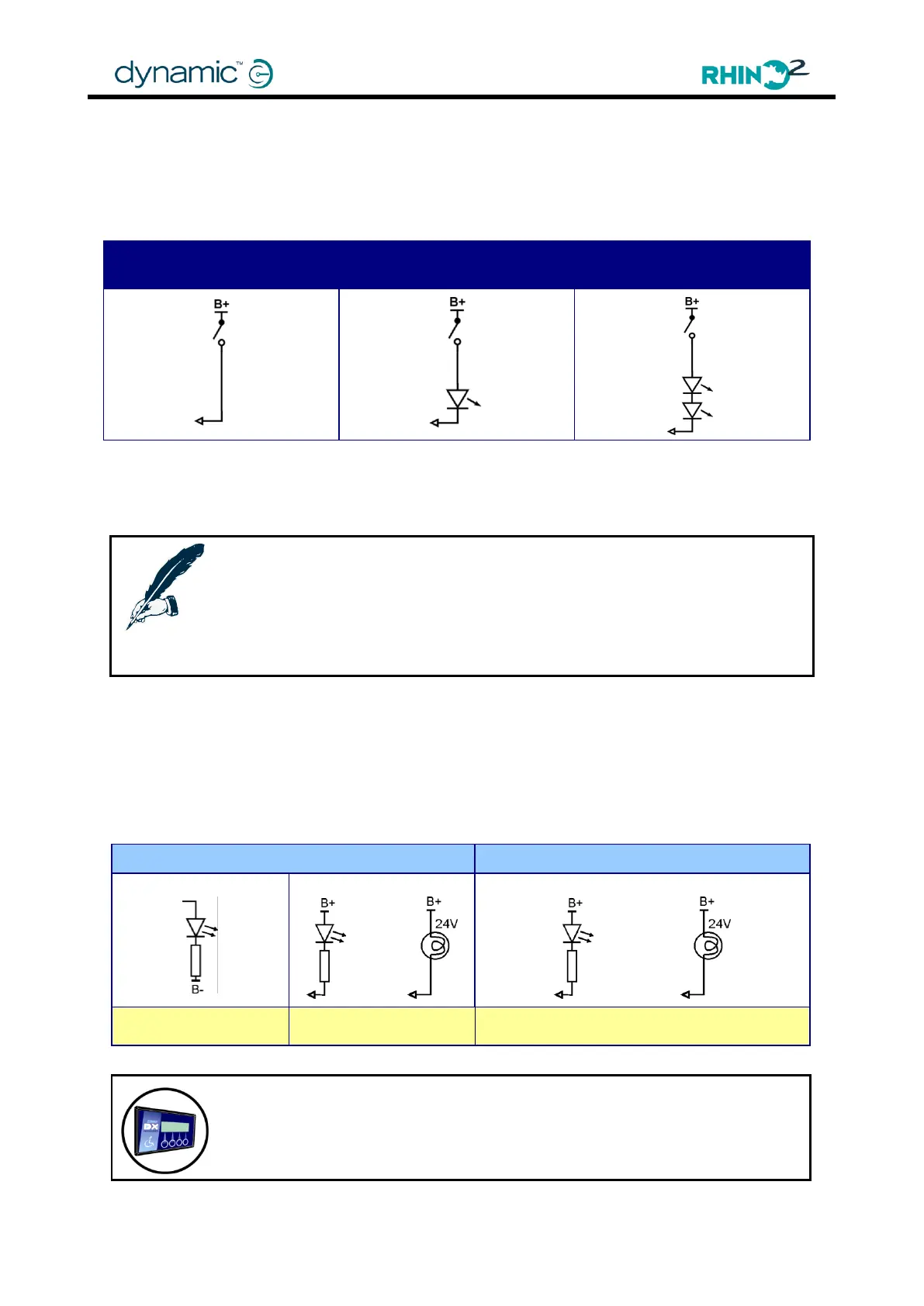
Key Switch with one
in-line Status LED
Key Switch with two
in-line Status LEDs
If there is no status LED wired in series with the key switch, set Key Switch Status LED (4.4.10.4)
to 'No' to decrease the current drain by 10mA when the RHINO2 is turned on.
Notes:
The voltage drop across the LED should be less than 5V at 10mA. If more
brightness is desired, two LEDs may be connected in series.
LEDs with voltage ratings, for example 12V or 24V, have internally fitted resistors
and must not be used.
3.10.10 Status Indicator Output
Pins 3, 10, and 11 on the tiller connector can be configured as dedicated status outputs. Pin
10 also has the ability to be active either high or low.
Pin 10 is rated for 50mA sink and 10mA source, whereas Pins 3 and 11 are capable of an
output up to 500mA. Select a resistor to limit LED current.
Pin 10 Status Output Options
Pin 3 and 11 Status Output Options
The status indicator can be configured to display 5 different types of diagnostics
flash code plus battery deep discharge warning.