Chapter 3: Installation and Testing
3.10.6 Speed Limit Pot Connections
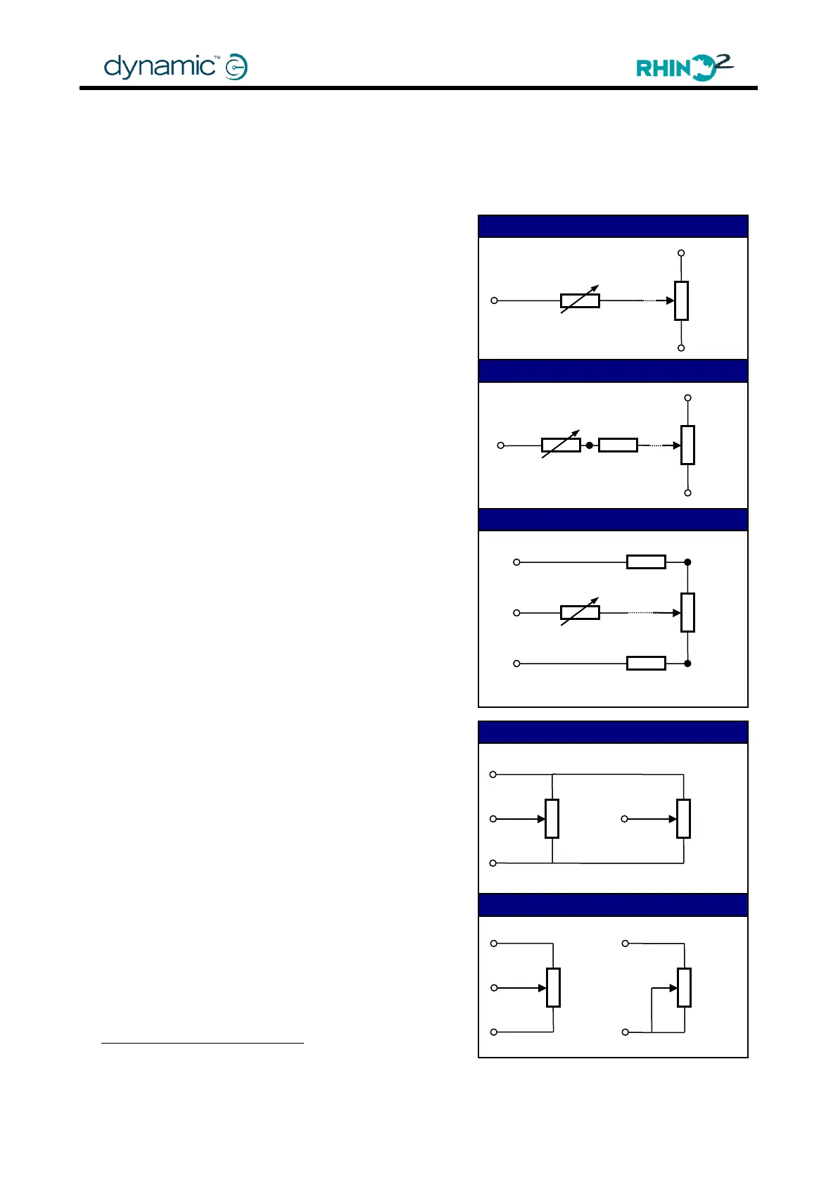
A speed limit pot may be connected either in series with the throttle wiper, or in parallel by
using the dedicated input Pin 9 (Speed Limit Pot wiper), Pin 2 (Throttle Positive) and Pin 8
(Throttle Negative).
3.10.6.1 In series with the throttle wiper
If wiring in series, use a 25kΩ potentiometer and set
Speed Limit Pot (4.4.2.11) to 'No', because the
dedicated speed pot input (pin 9) is not used.
To increase the chance of detecting faults in the
throttle wiring, use an ISO test resistor between the
throttle wiper and the speed pot. The ISO Test resistor
must be placed as close to the speed pot as possible,
preferably directly soldered with as short a lead as
possible and mechanically protected.
As an alternative to wiring a single ISO Test Resistor in
the Throttle Wiper, two ISO Test Resistors may be
added to the Throttle Positive and Throttle Negative
terminal of the throttle potentiometer. This will
decrease the susceptibility of the throttle circuit to
leakage. The 2 ISO resistors must be placed as close
to the throttle pot as possible, preferably directly
soldered with as short a lead as possible and
mechanically protected.
When ISO resistors are used, it may be necessary to
adjust the Throttle Configuration parameters (4.4.2).
3.10.6.2 In parallel with the throttle
For a speed pot in parallel, use a 100kΩ
potentiometer and set Speed Limit Pot to 'Yes'.
If the Speed Limit Pot is at its minimum position, the
speed of the scooter at full throttle deflection is set
by Minimum Forward Speed (4.4.3.7) and Minimum
Reverse Speed (4.4.3.8).
The Dual Decode variant already uses pin 9 for the
second throttle wiper connection. To use a separate
Speed Limit Pot in parallel to the throttle with this
variant, use a 10k log potentiometer. Connect it
between pin 4
and B-, and set Pin 4 Function
(4.4.9.1) to 'SRW' (Speed Reduction Wiper). If the
Speed Limit Pot is at its minimum position, the speed
of the scooter at full throttle deflection is set by the
Speed Reduction Wiper (SRW) parameters (4.4.3.15).
To avoid a throttle dead band when the speed is
Alternatively, connect between pin 6 and B-, or between pin 12 and B-, and set the relative
Pin [x] Function parameter to „SRW‟.
Speed Pot in Series with 2 ISO Resistors
Speed Pot in Series with ISO Resistor
Speed Pot in Parallel (Pin 9)
Speed Pot in Parallel (Pin 4)