When this function is active, the drive performance and
characteristics as defined in Profile 2 will be used. The primary
use of this function is to set a Reduce Speed mode.
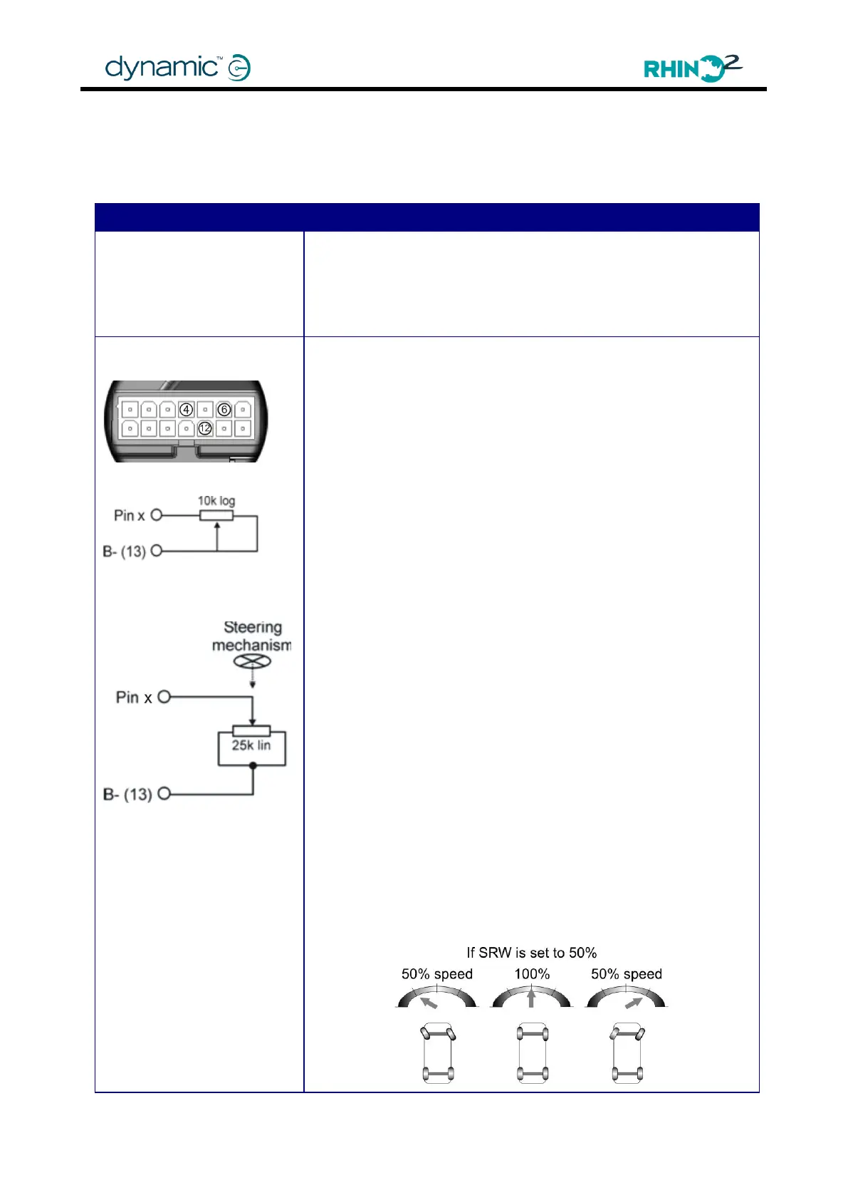
Available on Tiller Connector Pins 4, 6, 12, and 14 and
Charger/Programmer Connector Pin 4.
If Pin 4 Function (4.4.9.1), where „x‟ is 4, 6 or 12, is set to 'SRW', or
SRW (variable), it provides a variable speed reduction based on
the resistance between pin x and B- : decreasing the resistance
will decrease the speed of the scooter. Decreasing the
resistance to zero will slow down the scooter to a speed set by
the Speed Reduction Wiper (SRW) parameters (4.4.3.15).
Proportional speed reduction
As a conventional User Control potentiometer, the SRW
supports the use of a 10k logarithmic pot wired as a variable
resistor between Pin x (4, 6 or 12) and B– of the tiller.
SRW (variable) supports a user-defined resistance value,
between Pin x (4, 6 or 12) and B– of the tiller, which can be set
with SRW Scaling Resistor (Ohm).
To avoid a throttle dead band when the speed is reduced, use
the 'SRW Speed Scale' parameters and leave the 'SRW Speed
Limit' parameters at 100%.
Turning speed reduction
Alternatively, this function can be used as an anti-tip feature to
stop the scooter tipping while turning at a high speed, the
speed being reduced dependent on how far the tiller is turned.
In order for this function to work, mechanically connect the
wiper of the external pot to the steering mechanism during
installation. If the steering mechanism is in the centre position
(driving straight) the wiper should also be in the centre position,
providing maximum resistance. When the mechanism is turned
the wiper will move off-centre, which decreases the resistance
between pin x (4, 6 or 12) and B-, slowing down the scooter.
To avoid the scooter slowing down during a turn when it is
already driving at low speed, use the 'SRW Speed Limit'
parameters. Leave the 'SRW Speed Scale' parameters at 100%.