Chapter 3: Installation and Testing
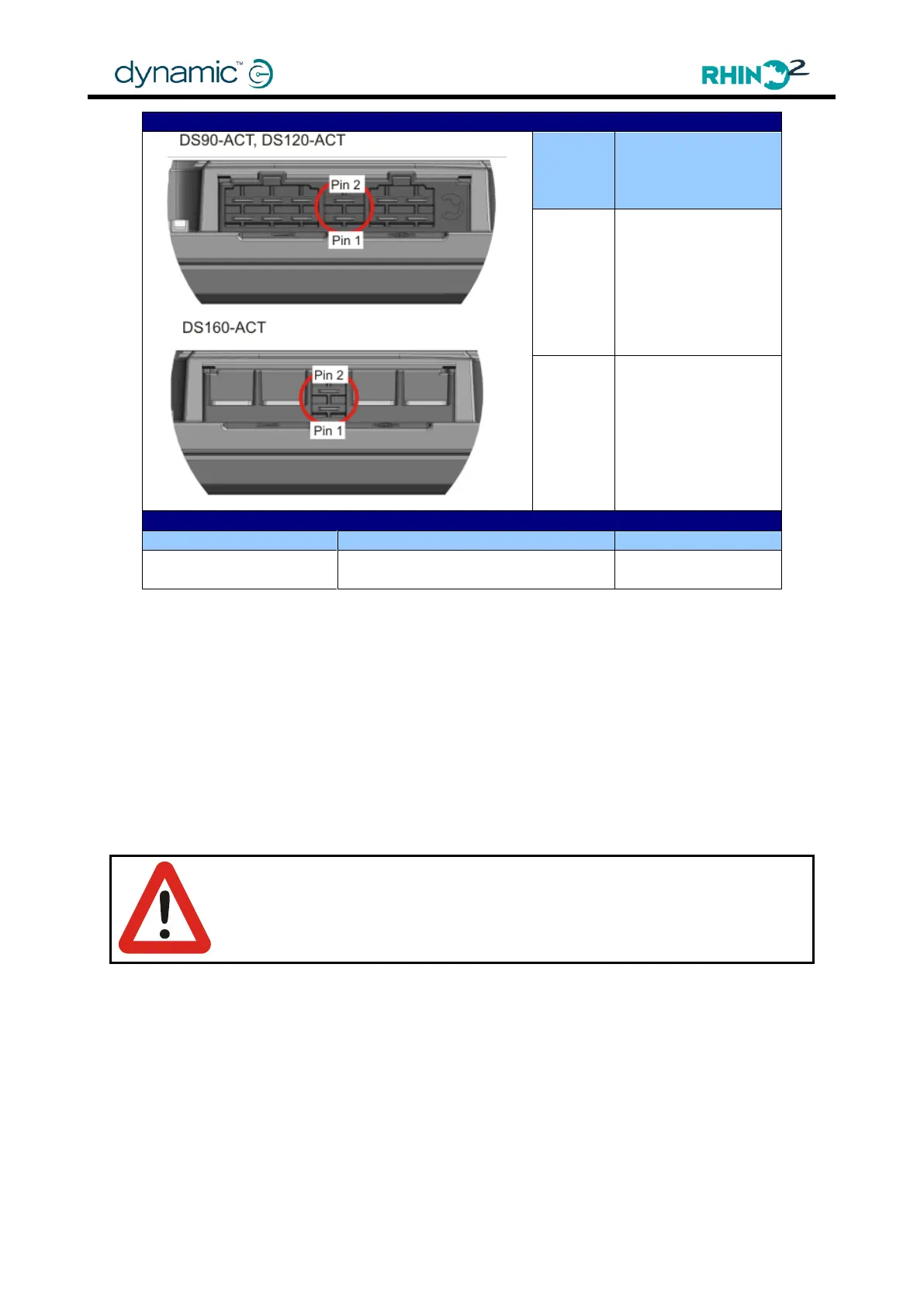
DS90-ACT,
DS120-ACT and
DS160-ACT (with
actuator)
Mating Connector Part Numbers
Crimp terminal female spade 18-
22AWG red insulated
Actuator Output
Power is supplied to the actuator through Pin 1 (Actuator Output A) and Pin 2 (Actuator
Output B) of the actuator connector. Actuator wiring should be a minimum of 0.8mm
2
(18AWG). The maximum current of the actuator output is 12.5A.
Drive Seat Select Switch
When the multifunction input pin (configured for actuator drive) is connected to Battery +,
the throttle controls driving as normal. When the multifunction input pin is not connected, the
throttle controls the actuator. Wiring the drive select switch through the key switch reduces
battery drain when 'drive' is selected and the scooter is off.
Warning:
To ensure safe operation of scooter with actuator, configure actuator
control by Wig-wag, limit max speed or inhibit drive when actuator is active
or in an unsafe position.