Digital Out
Setting
Description
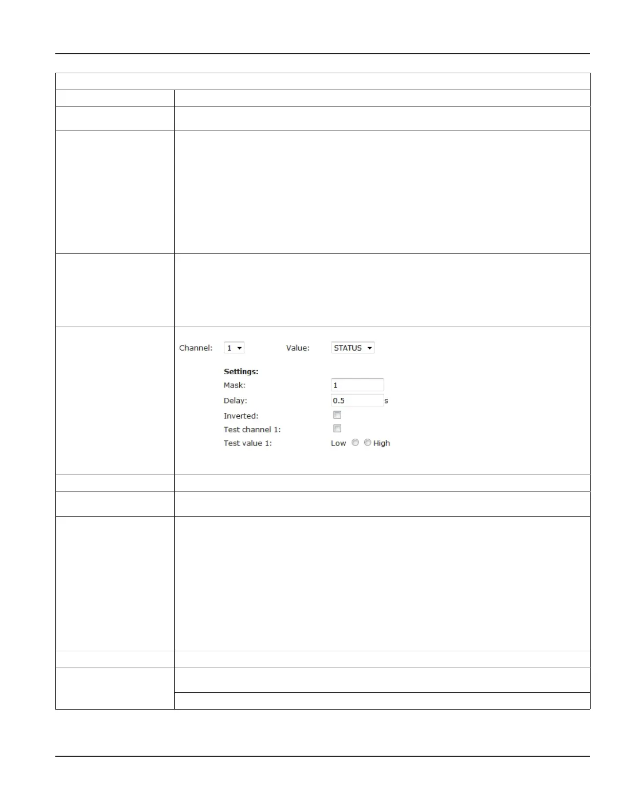
Channel
1…8
Available channels for assignment of values.
> Select channel for corresponding value from drop-down list.
Value
STATUS
Alarm
Pulse
HeartBeat
DoorContact
PulseAbs
PulsePos
PulseNeg
None
> Select value from drop-down list to define alarm signal via relay for selected parameters.
Value
STATUS
> Select STATUS for export of error message
The STATUS value corresponds in the software to a binary bit field where each bit reflects an
information. With the help of a bit mask this information can be filtered out and exported
through the digital output.
> STATUS = Error codes (= bit mask)
Settings
Mask
> Enter bit mask no. (currently 1 for bit mask error codes)
Delay > Enter time in s. Enter delay time in s between change of status and the setting of the digital
channel.
Inverted Option to invert digital output signal.
Tick checkbox to invert signal.
Example:
Mask value is 1.If bit 0 is set in STATUS the output signal is not active (de-energized), if bit 0 in
STATUSis not set the output signal isactive (energized).
Output signal is not inverted.
Example:
Mask value is 1.If bit 0 is set in STATUS field the output signal is active (energized), if bit 0 is not
set in STATUS, the output signal is not active (de-energized).
Test Channel 1
Tick checkbox to activate signal test.
Test value 1 Specify low or high signal.
low / high
Click Apply to save settings.
Programming
Page 67 March 2021 HYB-UM-03155-EN-03
 Loading...
