. . . . .
ACCOMPLISHING THE REFLOW PROCESS
Process Zones
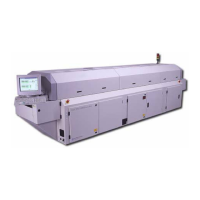
2-9317-372-00-0 Bravo™ 8105 Programming and Operations Guide 11-119
Process Zones
Introduction The goal of the reflow process is to melt the powder particles in the solder paste,
wet the surfaces being joined together, and solidify the solder to create a strong
metallurgical bond.
The following descriptions summarize each zone. A specific eutectic solder paste
(Sn63/Pb37) was referenced for any time/temperature examples. When creating
or troubleshooting a profile, always reference the solder paste’s manufacturer’s
specifications.
Preheat Zone Maximum slope is a time/temperature relationship that measures how fast the
temperature on the printed circuit board changes. The ramp–up rate is usually
somewhere between 1.0° C and 3.0° C per second, often falling between 2.0°
C and 3.0° C per second. The ramp–down rate is often ignored. It may be that
the ramp rate is less critical above certain temperatures, however, it seems that
the maximum allowable slope for any component should apply whether the
component is heating up or cooling down. It is a parameter to consider when
analyzing process results.
The preheat section is where the solvent begins to evaporate and a 2.0° — 3.0°
C (35.6° — 37.4° F) per second rise rate generally occurs. If the rate exceeds
this slope, potential damage to components from thermal shock or cracking is
risked. Solder paste can also have a spattering effect. If the rise rate (or
temperature level) is too low, evaporation of flux volatiles is incomplete.
Thermal Soak Zone The second section, thermal soak, is typically a 60 to 120 second exposure for
removal of solder paste volatiles and activation of the fluxes. The activated flux
components begin oxide reduction on component leads and pads.
Too high or too low a temperature can lead to solder spattering or balling as well
as oxidation of the paste, the attachment pads and the component terminations.
Similarly, fluxes may not fully activate if the temperature is too low. At the end of
the soak zone a thermal equilibrium of the entire assembly is desired just before
the reflow zone.
Reflow Zone The third section, the reflow zone, is also referred to as the “time above reflow”
or “time above liquidus” (TAL). The maximum temperature reached in the process
occurs in the reflow zone. Peak temperature is the maximum allowable
temperature of the entire process. The maximum temperature of the reflow
process is determined by the component on the assembly with the lowest
tolerance for high temperatures. (The component with the lowest “maximum
possible” temperature determines the component most susceptible to damage.)
Do not exceed that temperature. A standard guideline is to subtract 5° C from
the maximum temperature the most vulnerable component can sustain to arrive
at the maximum temperature for process.