PI-135 OPERATOR’S MANUAL
74
Profi le View Options:
The MAP profi le view pro vides sev er al options for
varying dis play pre sen ta tion. These op tions let you tai lor
the ap pear ance of the profi le dis play al low ing for improved
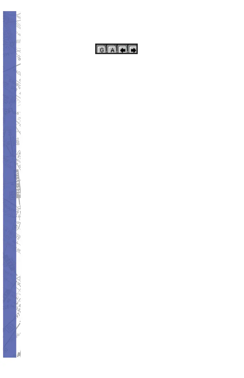
fl ight anal y sis. The four buttons lo cat ed at the bottom-right
of the MAP profi le display control these options.
Glideslope Limits:
The “G” (glideslope limits) but ton toggles the glideslope
limits overlay ON/OFF. This overlay graph i cal ly represents
the electronic glideslope signal limits of the specifi c
approach fl own. The “G” button and glideslope over lay
only become available after the prop er ILS fre quen cy has
been tuned in and the ap proach be gun. Color coding is
used to represent course de vi a tion as fol lows:
Yellow lines = half-scale, Red lines = full-scale
Altitude Grid:
The “A” (altitude grid) button toggles the altitude grid
lines. These lines are used in con junc tion with (and are
extensions of) the al ti tude scale markings on the right side
of the profi le display.
Profi le Scroll:
The two arrow buttons are used to scroll the profi le view
left and right respectively, and operate in de pen dent of the
main MAP view.
In combination with the four buttons pictured above, use
the ZOOM functions (previously explained) to get more
detailed MAP profi le views. While LOW (dis tant) ZOOM
levels are better for viewing the big pic ture, HIGH (close
in) ZOOM lev els are good for show ing minute fl ight path
and airspeed deviations.