PROline Prosonic Flow 93 FOUNDATION Fieldbus 3 Transducer Blocks (transmission blocks)
Endress+Hauser 103
3.3 Block output values
The Transducer Blocks make the following output values (process variables) available
to the downstream Analog Input function blocks:
• Transducer Block TRANSDUCER_CH1 (flow channel 1, base index 1200):
– Volume flow channel 1
– Sound velocity channel 1
– Flow velocity channel 1
– Signal strength channel 1
• Transducer Block TRANSDUCER_CH2 (flow channel 2, base index 1300):
– Volume flow channel 2
– Sound velocity channel 2
– Flow velocity channel 2
– Signal strength channel 2
• Transducer Block TRANSDUCER_CH1 and TRANSDUCER_CH2:
– Average volume flow
– Volume flow sum
– Volume flow difference
– Average sound velocity
– Average flow velocity
• Transducer Block TRANSDUCER_TOT (flow channel 2, base index 1550):
– Total izer 1
– Total izer 2
– Total izer 3
• The Transducer Blocks TRANSDUCER_DISP (display, base index 1500),
TRANSDUCER_DIAG (diagnosis, base index 1600) and TRANSDUCER_SERV
(service, base index 1650) do not have any output values.
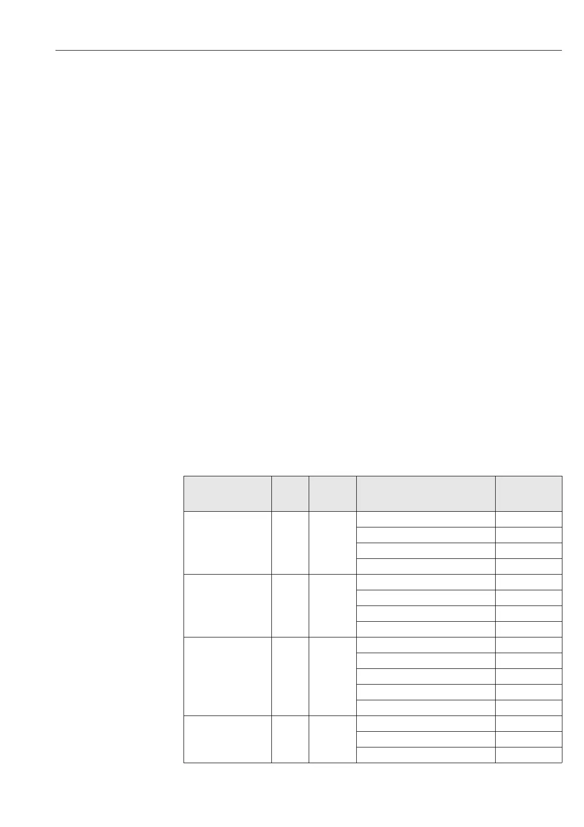
The CHANNEL parameter in the Analog Input function block, (see Page 171), is used to
assign the process variable which is read into and processed in the downstream Analog
Input function block.
The Transducer Block(s) in question must be in AUTO (automatic) mode for the process
variable to be processed correctly in the downstream Analog Input function block.
Transducer
Block:
Base
index
Operating
mode
Process variable:
Parameter
CHANNEL
(AI fct. block)
TRANSDUCER_CH1 1200 AUTO Volume flow channel 1 2
Sound velocity channel 1 21
Flow velocity channel 1 23
Signal strength channel 1 30
TRANSDUCER_CH2 1300 AUTO Volume flow channel 2 20
Sound velocity channel 2 22
Flow velocity channel 2 24
Signal strength channel 2 31
TRANSDUCER_CH1
+
TRANSDUCER CH2
1200
+
1300
AUTO
AUTO
Average volume flow 25
Volume flow sum 26
Volume flow difference 27
Average sound velocity 28
Average flow velocity 29
TRANSDUCER_TOT 1550 AUTO Totalizer 1 7
Totalizer 2 8
Totalizer 3 9

 Loading...


