1-12 General Information Rev. E
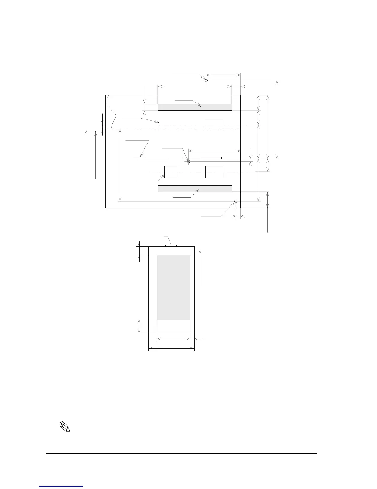
1.4.2.2 Printable Area for slip
Printable area for slip paper
*2 The length from the form stopper to the tip of the paper.
*3 The length from the tip of the paper to the first printing line position.
*4 The printable area after the slip BOF sensor detects the end of the paper. (The bottom margin
must be considered for a real printable area.)
*5 Bottom margin (calculated value).
Note:
Numeric values used here are typical values; consider this for the user design for the starting position in
the paper feeding direction.
Forward paper feed direction
Paper insertion direction
( 2 )
3.1
85.4
23.2
5.6
37.8
*3
( 8.1 )16.4
56.8
2
9
60
*2
Approx. 81.3
(For 461 steps)
Approx. 92.8
*4
Approx. 114.8
(MAX. 651 steps)
Slip ejection sensor position
The first printing line position
Paper feeding
roller position
Form stopper position
TOF sensor position
Sub-paper feeding
roller position
The last printing line position
4
*5
MIN . 18 . 4
BOF sensor position
PRINT
AREA
Paper inserting direction
Form stopper
5
18.4
(Min)
85.4(MAX)
68(Min)
5.6
(Units: mm)
 Loading...