Rev. E Setup 3-21
TM-H6000III Technical Reference Guide
NOTE:
Changes in DIP switch settings (excluding switches 2-7 and 2-8, interface reset signals) are recognized only when
the printer power is turned on or when the printer is reset. If the DIP switch setting is changed after the printer
power is turned on, the change does not take effect until the printer is turned on again or is reset.
If you turn on DIP switch 2-7 or 2-8 while the printer power is turned on, the printer may be reset, depending on
the signal state. DIP switches should not be changed while the printer power is on.
If the print density is set to level 3 or 4, print speed is reduced as follows:
Maximum 180mm/s at 24V, 25°C in level 3
Maximum 170mm/s at 24V, 25°C in level 4
For a tip about print density, see “When Using Original Paper” (page 3-23).
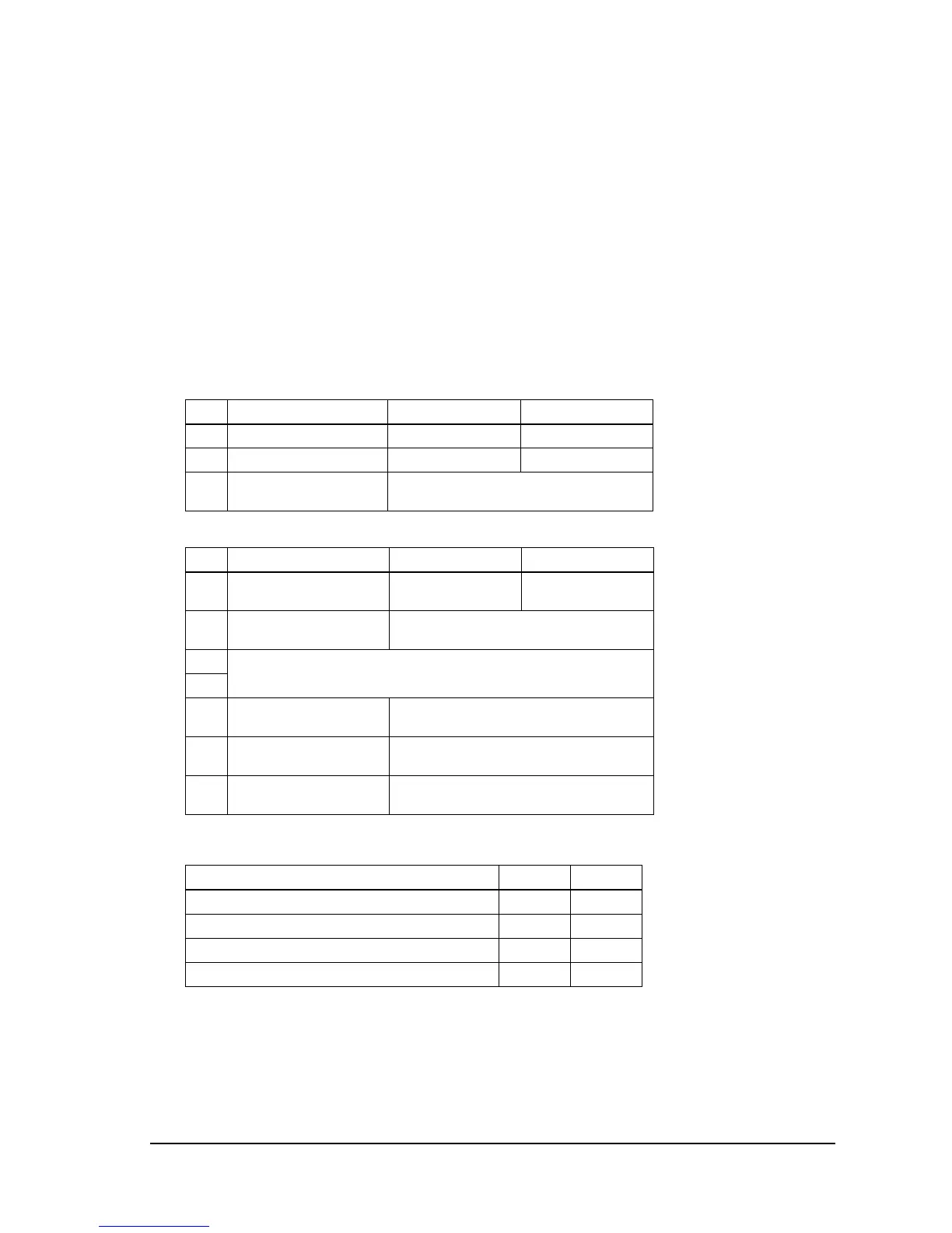
3.4.3.3 Parallel / Ethernet interface model
Print density
DIP Switch 1
SW Function ON OFF
1-1 Auto line feed Always enabled Always disabled
1-2 Receive buffer capacity 45 bytes 4KB
1-3~
1-8
Reserved Fixed to OFF
DIP Switch 2
SW Function ON OFF
2-1 Handshaking
(BUSY condition)
Receive buffer full Offline or receive
buffer full
2-2 Internal use (Do not
change setting.)
Fixed to OFF
2-3 Print density (See the table below.)
2-4
2-5~
2-6
Internal use (Do not
change setting.)
Fixed to OFF
2-7 Reserved (for serial
interface)
Fixed to OFF
2-8 I/F pin 31 reset signal
(Do not change setting.)
Fixed to ON
Print Density SW 2-3 SW 2-4
1 (Light) ON ON
2↑ OFF OFF
3↓ ON OFF
4 (Dark) OFF ON
 Loading...