EasyManuals Logo
Home>Epson>Controller>RC700 Series

Epson RC700 Series User Manual

Epson RC700 Series
316 pages
To Next Page IconTo Next Page
To Previous Page IconTo Previous Page
Page #105 background imageLoading...
Page #105 background image
Setup & Operation 14. Option Slots
RC700 / RC700-A Rev.23 93
14.4.5 Communication Cable (RS-232C)
Prepare a communication cable as described in this section.
Connector
Standard
RS-232C Connector (Controller side)
D-sub 9 male pin
Mounting style #4 - 40
Use twisted pair cable for shielded wire.
Clamp the shield to the hood for noise prevention.
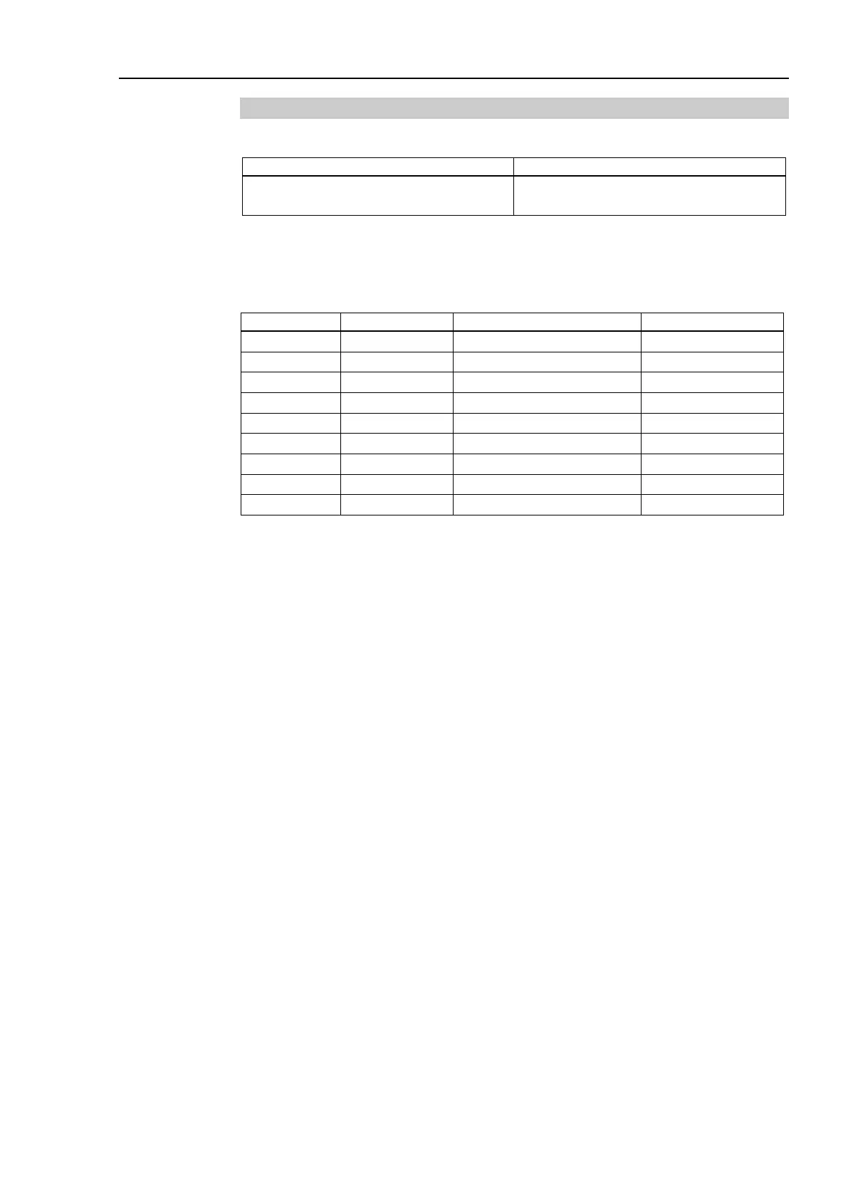
Pin assign of the RS-232C connector is as follows.
Pin No
Signal
Function
Signal Direction
1
DCD
Data carrier detect
Input
2
RXD
Receive data
Input
3
TXD
Send data
Output
4
DTR
Terminal ready
Output
5
GND
Signal ground
-
6
DSR
Data set ready
Input
7
RTS
Request to send
Output
8
CTS
Clear to send
Input
9
RI
Ring indicator
Input
NOTE

Table of Contents

Other manuals for Epson RC700 Series

Questions and Answers:

Question and Answer IconNeed help?

Do you have a question about the Epson RC700 Series and is the answer not in the manual?

Epson RC700 Series Specifications

General IconGeneral
BrandEpson
ModelRC700 Series
CategoryController
LanguageEnglish

Related product manuals