Setup & Operation 14. Option Slots
RC700 / RC700-A Rev.23 99
(4) Shield Configuration
“Frame Ground” and “User Ground” of the shield: CN4, CN5, CN6, and CN7
1-2 pin short : Frame ground (FG) shield configuration.
When you want to spread the shield noise to the robot
controller side.
2-3 pin short : User ground (UG) shield configuration.
When you want to insulate the shield by external connection
device and robot controller.
Or when you want to spread the shield noise to the external
connection device side.
User Ground (UG): Analog ground (AGND) on the external connection device side.
Frame Ground (FG): Digital ground (DGND) inside the robot controller.
DAC1ch
Not Use Not Use Not Use
DAC2ch
Not Use
Not Use Not Use
ADC1ch
Not Use Not Use
Not Use
ADC2ch
Not Use Not Use Not Use
*: Default
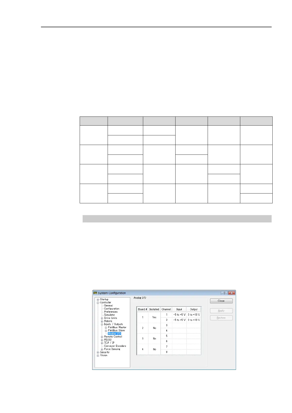
14.6.3 Confirmation with EPSON RC+ (Analog I/O Board)
The Controller software automatically identifies the analog I/O board when mounting
analog I/O board to the optional unit of the controller.
Therefore, no software
configuration is needed.
Correct identification can be confirmed from EPSON RC+.
(1) Select the EPSON RC+ 7.0 menu-[Setup]-[System Configuration] to display the
[System Configuration] dialog.
(2) Select [Controller]-[Inputs / Outputs]-[Analog I/O].

 Loading...


