Setup & Operation 12. I/O Remote Settings
RC700 / RC700-A Rev.23 75
12.2 Timing Specifications
12.2.1 Design Notes for Remote Input Signals
The following charts indicate the timing sequences for the primary operations of the
Controller.
The indicated time lapses (time durations) should be referred to only as reference values
since the actual timing values vary depending on the number of tasks running, as well as
CPU speed of the Controller. Check carefully and refer to the following charts for the
timing interrelation when you enter an input signal.
During system design, make sure that you actuate only one remote input operation at a
time, otherwise an error will occur.
The pulse width of an input signal must be 25 or more milliseconds to be detected.
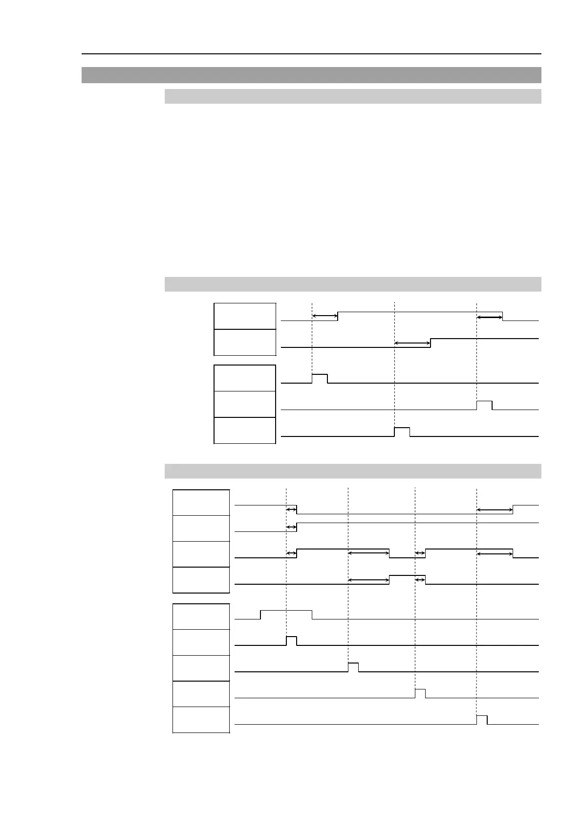
12.2.2 Timing Diagram for Operation Execution Sequence
[Unit: msec]
12.2.3 Timing Diagram for Program Execution Sequence
* The duration varies depending on the Quick Pause (QP) setting and the program’s
operating status at the time of Pause input [Unit: msec]

 Loading...


