Setup & Operation 14. Option Slots
104 RC700 / RC700-A Rev.23
14.8 EUROMAP67 Board
EUROMAP67 is a standardized interface for communications between
Western-manufactured injection molding machines (IMM) and robots.
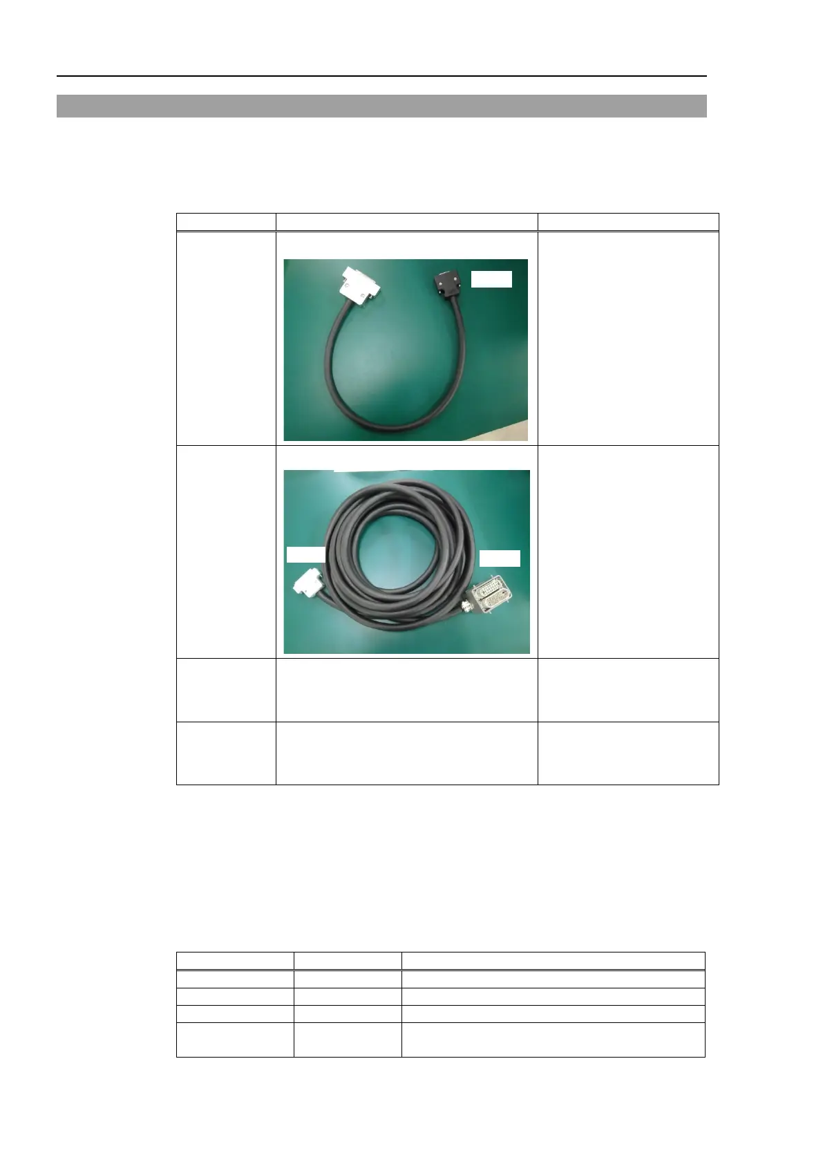
List of accessories
2194667
EUROMAP67 Cable1
Emergency Stop cable
(CN2)
2194667
EUROMAP67 Cable2
Connection cable
Robot Controller(CN1)
- IMM(CN4)
2165789 EUROMAP67Emergency Connector Plug
For emergency stop switch
wiring
Soldering plug (CN3)
2194882 EUROMAP67Emergency Connector
Shell
For emergency stop switch
wiring
Shell kit (CN3)
Wire the emergency stop switch wiring connector (CN3).
Reference: Setup & Operation 9. EMERGENCY
The connector signal placement is described below.
Setup & Operation 14.8.11 Emergency stop connecter Pin Assignments
List of connectors used
10126-3000PE, 10326-52K0-008
10136-3000PE, 10336-52K0-008
CN4 Tyco
T1319320125-000 / T2020252201-000 /
T2020252101-000

 Loading...


