EasyManuals Logo

Epson RC700 Series User Manual

Epson RC700 Series
316 pages
To Next Page IconTo Next Page
To Previous Page IconTo Previous Page
Page #136 background imageLoading...
Page #136 background image
Maintenance 3. Controller Structure
124 RC700 / RC700-A Rev.23
3. Controller Structure
3.1 Location of Parts
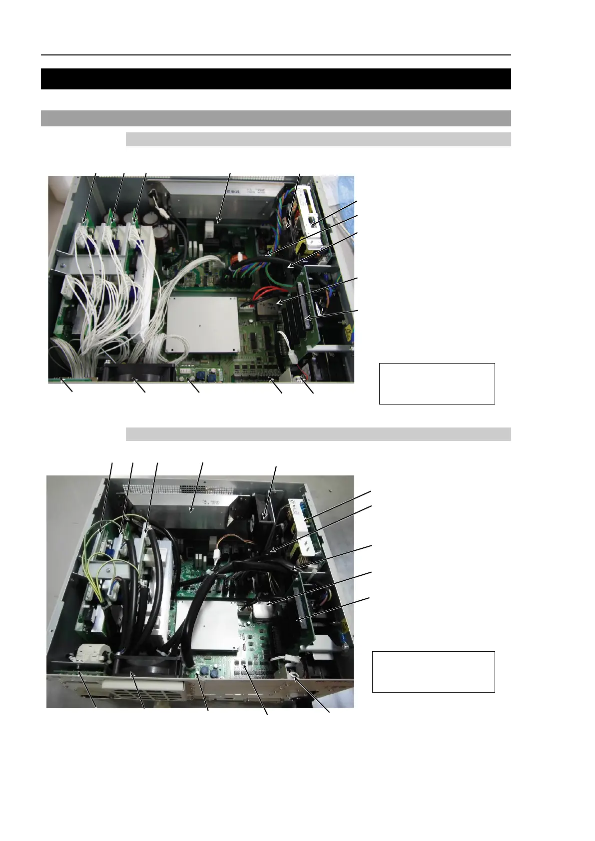
3.1.1 RC700
MDB2
DPB
MDB1
DMB
CF
MDB3
24V Switching Power Supply Module
Fan
(Front Fan)
5V Switching Power Supply Module
15V Switching Power Supply Module
Option Slots
Battery
DMB-LED Board
DMB-SUB Board
NOTE
MDB : Motor Drive Board
DMB : Drive Main Board
DPB : Drive Power Board
15V Switching Power Supply Module
3.1.2 RC700-A
MDB2
Regenerative
Resistor
24V Switching Power Supply Module
MDB1
Fan1
(Front Fan)
DMB-SUB Board
DMB
5V Switching Power Supply Module
Fan 2 (Regenerative Fan)
Option Slots
CF
Battery
MDB3
DMB-LED Board
NOTE
MDB : Motor Drive Board
DMB : Drive Main Board
DPB : Drive Power Board
15V Switching Power Supply Module
* MDB3 is not supplied for G1, G3, G6, G10, G20, and RS.

Table of Contents

Other manuals for Epson RC700 Series

Questions and Answers:

Question and Answer IconNeed help?

Do you have a question about the Epson RC700 Series and is the answer not in the manual?

Epson RC700 Series Specifications

General IconGeneral
ModelRC700 series
CategoryController
Programming LanguageSPEL+
Safety StandardISO 10218-1
TypeRobot Controller
Communication InterfaceEthernet, RS-232, USB
Operating Temperature0°C to 45°C (32°F to 113°F)
Humidity20% to 80% (non-condensing)
Number of controllable robots4

Related product manuals